
Parallel pneumatic gripper

a pneumatic gripper and parallel technology, applied in the field of pneumatic grippers, can solve the problems of limited clamping power, limited space available for forming the piston chamber(s), and drawbacks of pneumatic grippers, and achieve the effects of improving performance, reliable operation, and large diameter

Active Publication Date: 2013-11-19
GIMATIC SRL
View PDF10 Cites 7 Cited by
  • Summary
  • Abstract
  • Description
  • Claims
  • Application Information

AI Technical Summary

Benefits of technology

This design increases clamping power, reduces volume and weight, ensures reliable operation, and prevents dirt and fluid penetration, achieving a higher degree of protection and efficiency compared to conventional grippers.

Problems solved by technology

However, such pneumatic grippers are not without drawbacks and disadvantages.
Clearly, the presence of the longitudinal seats for the guide columns, situated parallel with to the sides of the control pistons within the same gripper body, limits the space available for forming the piston chamber(s).
Consequently, the chamber or each chamber has a bore which is limited in size or, in any case, relatively small compared to the transverse dimensions of the gripper body, so that each piston will have a diameter which is equally small, resulting in a limited clamping power.
Therefore, under these conditions, in order to achieve a higher clamping power, it is necessary to employ grippers larger in size which disadvantageously occupy a larger volume and are also heavier as well as difficult to be manufactured.
The stems of the pistons and the guide columns may be provided with seals, but according to the solutions provided hitherto by the prior art, the wear of these seals results in the penetration of dirt and / or fluids into the gripper body, in which case the gripper has to operate in wet environments which can reduce the efficiency and working life of the tool.

Method used


Image

  • Parallel pneumatic gripper
  • Parallel pneumatic gripper
  • Parallel pneumatic gripper

Examples


Embodiment Construction

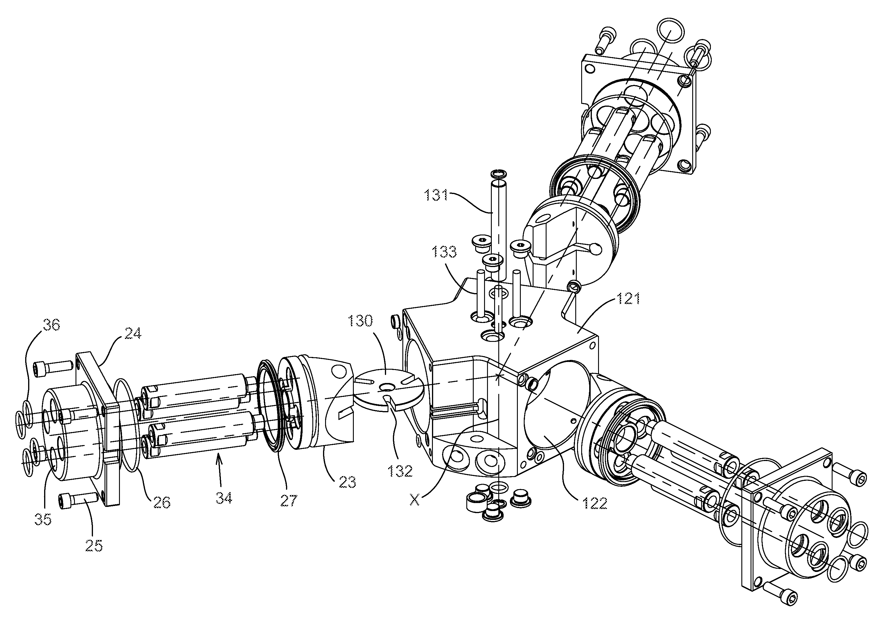
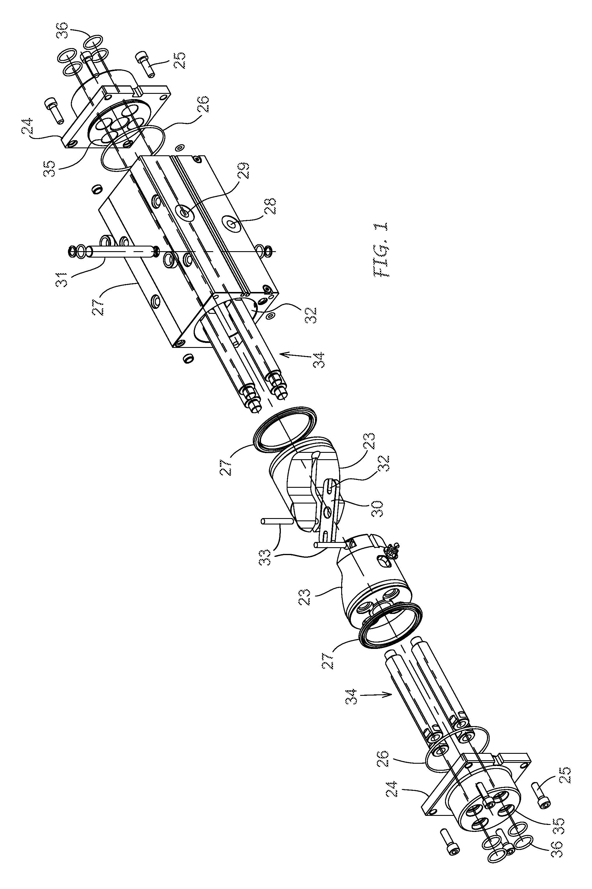
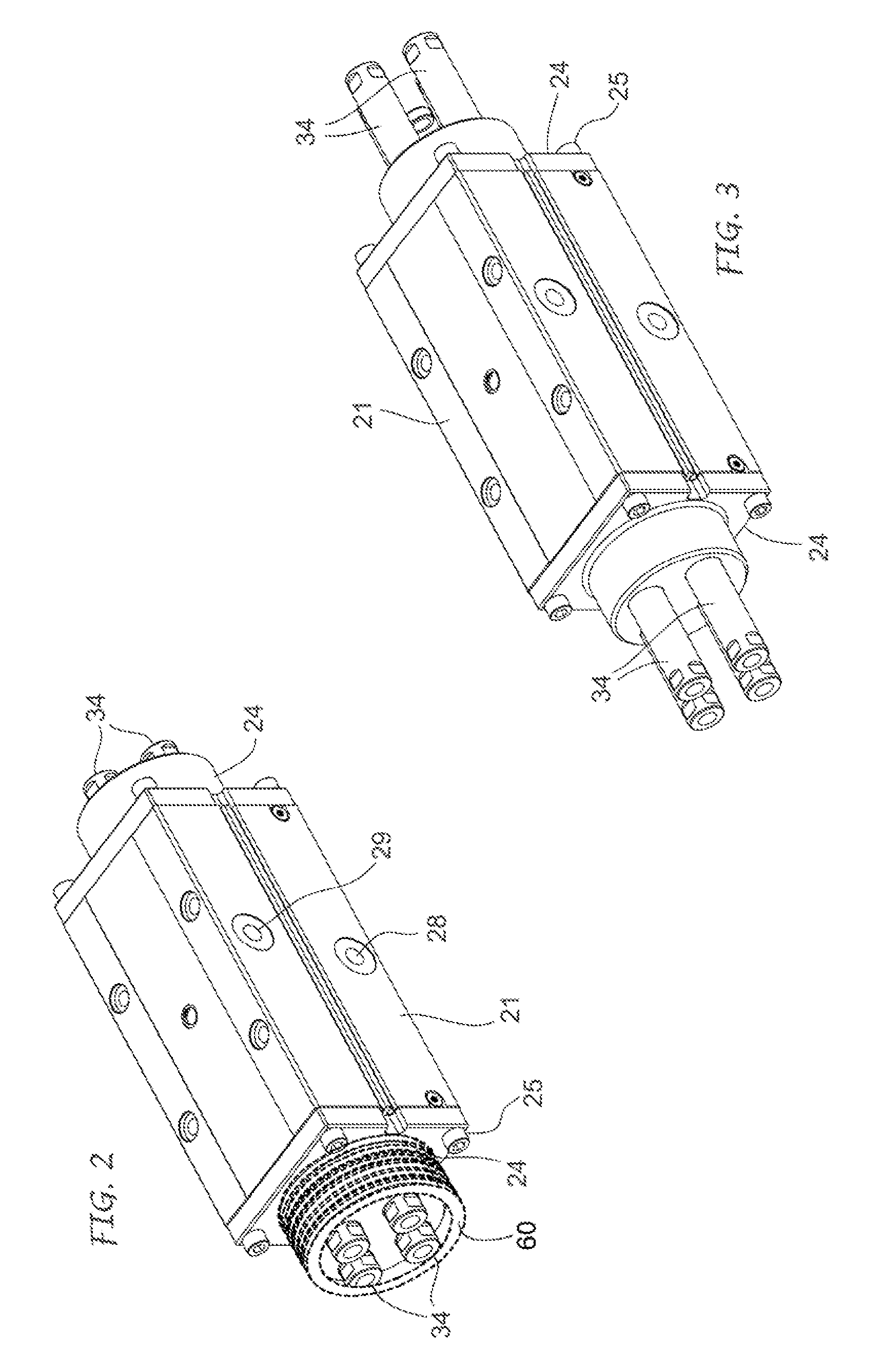
[0032]In the embodiment shown in FIGS. 1-7, the gripper according to the invention comprises a gripper body 21 which defines internally a longitudinal chamber 22 accommodating two pneumatic control pistons 23 which are aligned.

[0033]Preferably, the gripper body 21 is formed from an extruded shape with a square cross-section and an axial cavity. The longitudinal chamber 22 is closed at its opposite ends by two heads 24 which are each attached to the gripper body by means of screws 25 and at least one intervening seal 26. The longitudinal chamber 22 may be cylindrical and, therefore, the pneumatic control pistons 23 will have a cross-section and a diameter corresponding to those of said chamber.

[0034]In particular, the control pistons 23 are arranged in-line and are movable within the chamber 22 in opposite directions, so as to be alternately moved towards and away from each other. In order to allow the pistons to be moved close to each other while limiting their overall length, the f...


PUM


Abstract

The invention relates to a pneumatic gripper which comprises a gripper body (21,121), at least two pneumatic control pistons (23) operating within at least one chamber (22,122) defined by the gripper body and movable in opposite directions with respect to each other by a driving fluid supplied to the chamber, at least two guide columns (34) associated with each piston and emerging from the ends of at least the chamber, and at least two jaws (37) movable with the pistons between an active position for gripping a work-piece and an inactive position for releasing the work-piece. The guide columns (34) are attached directly in front of and inside the profile of a respective piston (23), and each gripping jaw (37) may be attached directly to the ends of the columns of a relevant control piston.

Description

FIELD OF THE INVENTION[0001]The present invention relates generally to the field of pneumatic grippers for gripping various parts, objects or bodies during the stages of production and / or handling and / or assembly thereof by means of robot systems, and it relates particularly to a parallel pneumatic gripper having at least one pair of gripping jaws linearly movable in opposite directions for opening and closing the jaws by means of a single-acting or double-acting pneumatic control system.BACKGROUND ART[0002]In the field considered here, pneumatic grippers of varying configuration, size and gripping or clamping power are already known and available. Also known among these various types of pneumatic grippers are parallel grippers of the so-called long-stroke or wide-opening type, which essentially comprise a gripper body, two pneumatic control pistons operating within said body, movable in opposite directions with respect to each other and each having a coaxial pushing / pulling stem, t...

Claims


Application Information

Patent Timeline
Patent Type & Authority Patents(United States)
IPC IPC(8): B25J15/08
CPCB25J15/0253B25J15/0293B25J15/086B25J15/10
Inventor MAFFEIS, GIUSEPPE
Owner GIMATIC SRL
Learn More