Motor/pump assembly

a technology of motors and components, applied in the direction of liquid fuel engines, positive displacement liquid engines, vehicle sub-unit features, etc., can solve the problems of entanglement of the motor, the vacuum pump cannot be driven or temporarily cannot be driven by the internal combustion engine, and the power output of the internal combustion engine is appreciable. , to achieve the effect of disproportionally high outlay

Active Publication Date: 2013-11-19
CONTINENTAL TEVES AG & CO OHG
View PDF21 Cites 29 Cited by
  • Summary
  • Abstract
  • Description
  • Claims
  • Application Information

AI Technical Summary

Benefits of technology

[0009]The object is achieved, according to aspects of the invention, in that the outlet ducts are arranged in the working-space covers and in the pump casing in such a way that air displaced out of the working spaces is conducted into an inner space, surrounding the crank drive, of the pump casing, and in that an air outlet unit is provided, which allows a low-noise blow-out of the air from the inner space as a result of the deflection of the air. The inner space, also called the crank chamber, thus serves as a sound-damping space, since the blown-out air is not conducted directly into the atmosphere. Owing to the deflection of the air in the air outlet unit, the noise level can additionally be lowered appreciably, so that the blow-out noises are virtually avoided.
[0040]According to an advantageous development of the motor / pump assembly according to aspects of the invention, to make it easier to mount the working-space cover, the pump casing and the working-space covers have means for the defined positioning of the working-space covers on the pump casing.

Problems solved by technology

Nevertheless, an appreciable fraction of the power output by the internal combustion engine has to be expended in order to drive such a pump.
Furthermore, in vehicles with an electric or hybrid drive, the vacuum pump cannot be driven or temporarily cannot be driven by the internal combustion engine.
Equipping such an electrically driven pump with a lubricant circuit or connecting it to such would entail a disproportionally high outlay.
On account of vibrations, the known diaphragm pumps mostly cannot fulfil these requirements or demand a high outlay in terms of sound-damping measures.

Method used


Image

  • Motor/pump assembly
  • Motor/pump assembly
  • Motor/pump assembly

Examples


Embodiment Construction

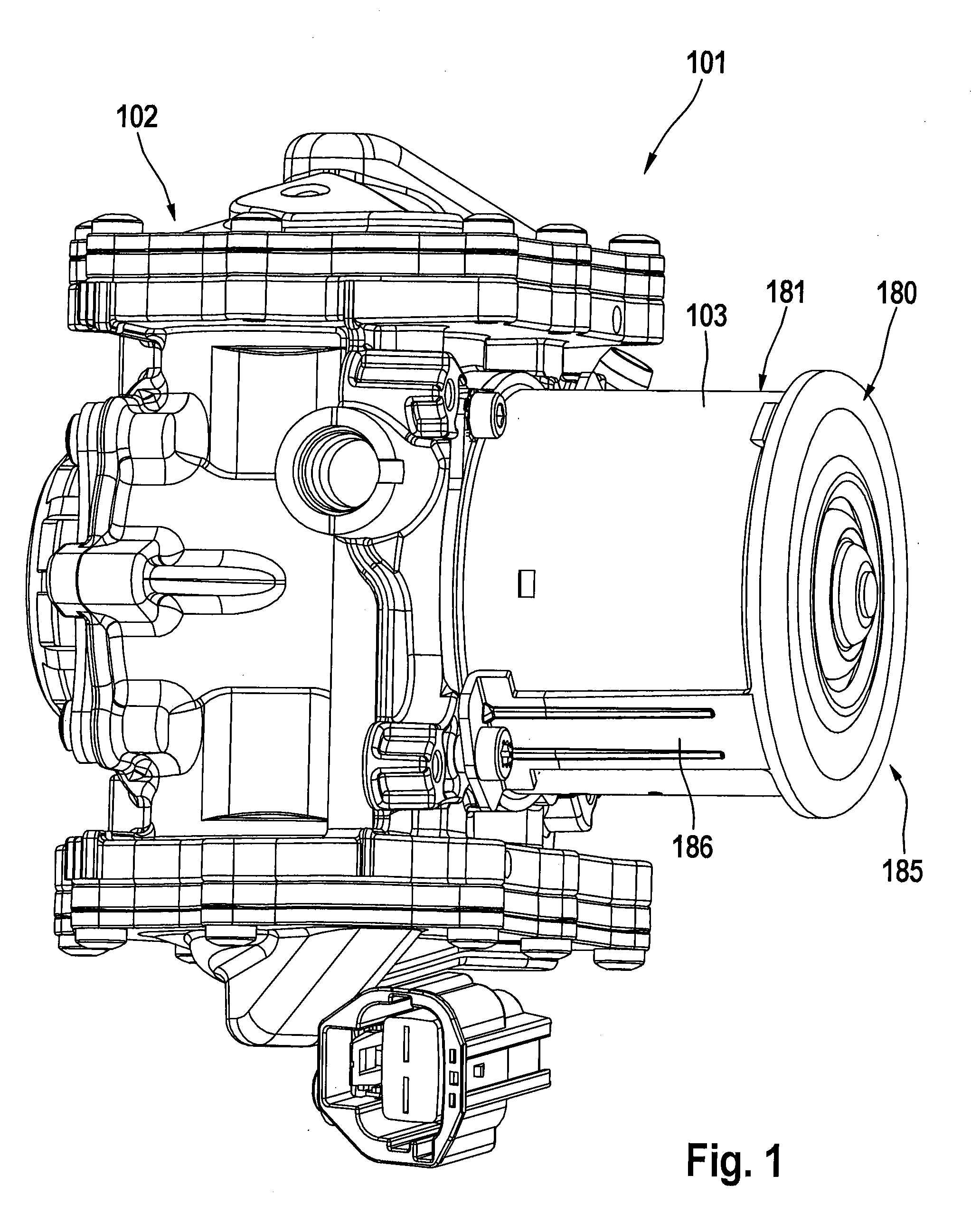
[0056]FIGS. 1 to 7 show an exemplary embodiment of a motor / pump assembly 101.

[0057]FIG. 1 shows the motor / pump assembly 101 in a three-dimensional illustration, which comprises a pump 102 with a pump casing 105 and an electric motor 103 driving the pump 102, in this case the motor 103 may, for example, be designed as a direct-current motor.

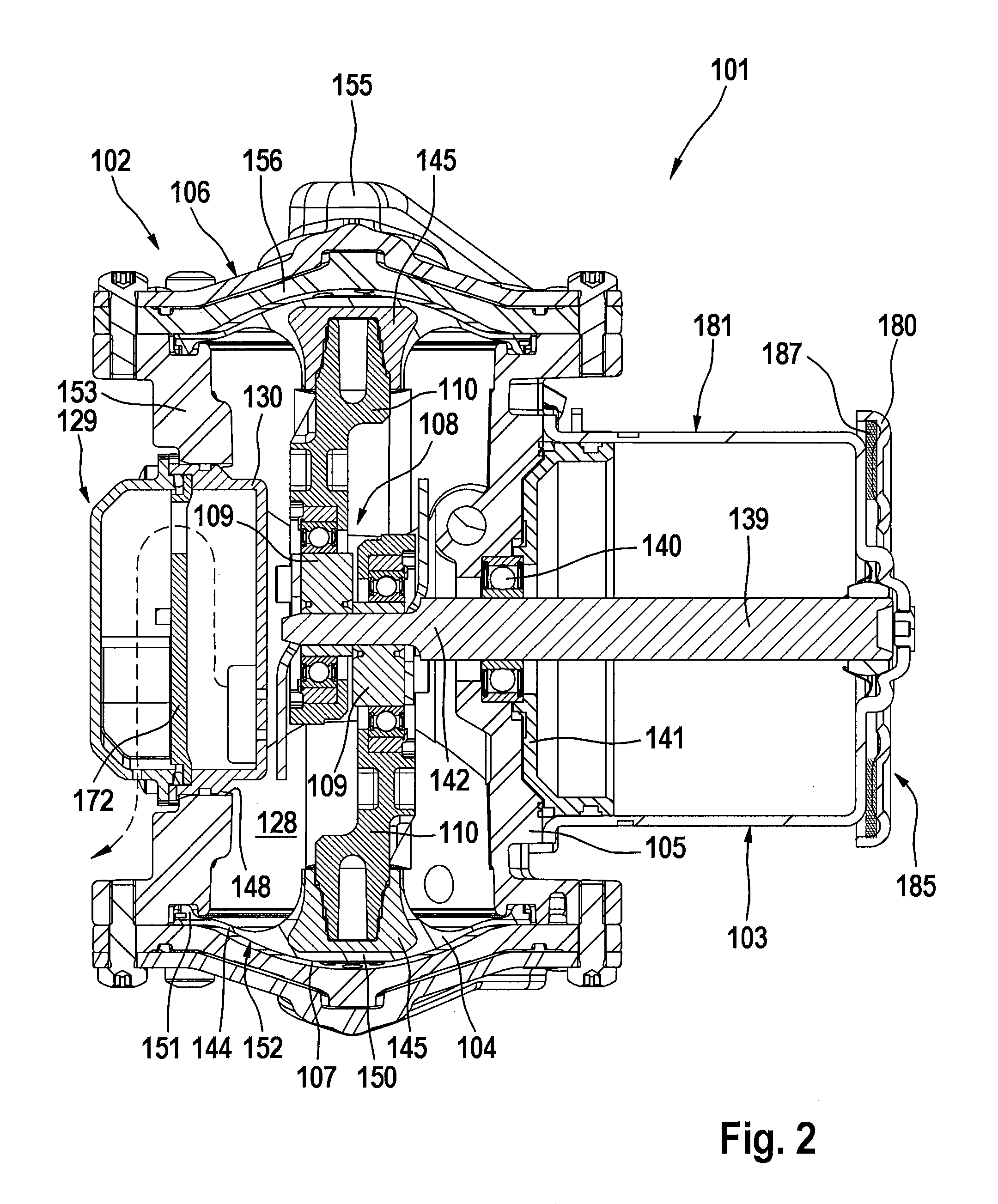
[0058]As can be gathered particularly from FIG. 2, which shows the motor / pump assembly 101 in a longitudinal section through a first plane, the pump 102 is provided as a double-diaphragm pump with two mutually opposite working diaphragms 104 which are tension-mounted in each case between the pump casing 105 and a working-space cover 106 and which thereby delimit a working space 107. The working diaphragms 104 can be moved contradirectionally by means of a crank drive 108 with comprises, for each working diaphragm 104, an eccentric 109 and a connecting rod 110.

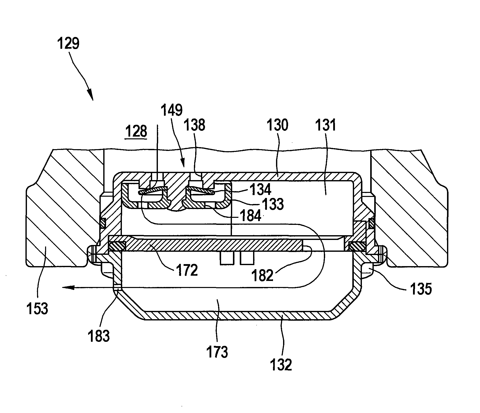
[0059]The working-space cover 106 of the motor / pump assembly 101 is illustrated in sectio...


PUM


Abstract

A motor / pump assembly for a motor vehicle brake system including a pump and a motor driving the pump, the pump having opposite working diaphragms which are, in each case, mounted between a pump casing and a cover and thereby delimit a space and which can be moved by a crank drive, the space being assigned, in each case, an inlet duct with an inlet valve and an outlet duct with an outlet valve. The outlet ducts are arranged in the covers and in the pump casing such that air displaced out of the spaces is conducted into an inner space surrounding the crank drive of the pump casing and that an air outlet unit be provided, which allows a low-noise blow-out of the air from the inner space as a result of the deflection of the air.

Description

CROSS REFERENCE TO RELATED APPLICATIONS[0001]This application is the U.S. national phase application of PCT International Application No. PCT / EP2008 / 061836, filed Sep. 8, 2008, which claims priority to German Application No. 10 2007 043 054.1, filed Sep. 11, 2007, and German Application No. 10 2008 005 820.3, filed Jan. 24, 2008, the contents of such applications being incorporated by reference herein.FIELD OF THE INVENTION[0002]The invention relates to a motor / pump assembly, in particular for the provision of pressure for a brake actuation device of a motor vehicle brake system with a pneumatic brake booster, in particular with a vacuum brake booster, comprising a pump and an electric motor driving the pump, the pump being provided as a double-diaphragm pump with two mutually opposite working diaphragms which are in each case tension-mounted between a pump casing and a working-space cover and thereby delimit a working space and which can be moved by means of a crank drive having ec...

Claims


Application Information

Patent Timeline
Patent Type & Authority Patents(United States)
IPC IPC(8): F04B39/00
CPCB60T17/008B60T17/02F04B39/0055F04B39/121F04B43/026F04B43/04B60Y2400/81B60Y2306/09
Inventor BACHER, JENSMILISIC, LAZARRITTER, WOLFGANGSEITZ, KARLHEINZRUFFER, MANFREDGONZALEZ, JOSESTAHL, THOMASJURGING, MICHAELQIAN, YUEJUN
Owner CONTINENTAL TEVES AG & CO OHG
Why Eureka
Try Eureka