Method of controlling longitudinal properties of optical fiber

a technology of optical fiber and longitudinal properties, which is applied in the field of fabricating optical fiber, can solve the problems of limited the capabilities of these fibers, significant length-dependent variation in one or more of these characteristics, and inability to meet the requirements of the application of the fiber, so as to achieve the effect of restoring fiber strength, simplifying the inventive process of exposing the optical fiber, and maintaining strength

Active Publication Date: 2013-11-26
OFS FITEL LLC
View PDF17 Cites 1 Cited by
  • Summary
  • Abstract
  • Description
  • Claims
  • Application Information

AI Technical Summary

Benefits of technology

[0016]The dopants used to create various types of fibers / regions (e.g., Ge, P, F) may also be adjusted / modified to introduce another variable into the use of actinic radiation to impart desired length-dependent changes to an optical fiber's characteristics. For example, phosphorous may be used as a core dopant in addition to germanium to provide for two different components that may be adjusted to modify the dispersion as a function of fiber length. The core dopant distribution may also be varied in the radial direction so that the actinic radiation exposure produces an index change which varies as a function of the core radius and effectively alters the radial index profile of the fiber.
[0018]For optical filtering applications, it is often desirable to maintain a constant cutoff wavelength for the fundamental (LP01) mode (or higher-order modes in special applications). However, a small decrease in the core diameter (e.g., from 2.59 μm to 2.46 μm) shifts the LP01 mode cutoff wavelength from 1.606 μm to 1.524 μm—a highly undesirable result for filter applications. Therefore, the technique of the present invention may be used to compensate for this undesirable decrease in core diameter by increasing the core index from 0.025 Δn to 0.027 Δn such that the LP01 cutoff wavelength is maintained at the desired 1.606 μm value. It is further possible that the attenuation at different wavelengths may be monitoring during the index modification process to provide useful feedback on the index change required to achieve the desired tuning of the cutoff wavelength.

Problems solved by technology

While various specialized processes have been developed to fabricate specialized preforms from which these fibers are drawn, the as-drawn fiber may exhibit length-dependent variations which are unacceptable.
Length-dependent variations in nonlinear characteristics such as chromatic dispersion, polarization mode dispersion, birefringence, zero dispersion wavelength, cutoff wavelength (for both fundamental and higher-order modes), stimulated Brillouin scattering (SBS) characteristics and the like have limited the capabilities of these fibers.
However, in applications where relatively long lengths of fiber are required, any significant length-dependent variation in one or more of these characteristics may be problematic.
However, when it is desired to use longer lengths of HNLF for other applications, the non-uniformity of the chromatic dispersion profile as a function of fiber length becomes problematic.
While this method is suitable for use in improving the uniformity of the refractive index profile of a standard profile, such a method is not considered useful in controlling various parameters in many of today's specialized fibers, where the draw process itself is known to introduce slight variations in fiber diameter sufficient to create undesired length-dependent variations.

Method used


Image

  • Method of controlling longitudinal properties of optical fiber
  • Method of controlling longitudinal properties of optical fiber
  • Method of controlling longitudinal properties of optical fiber

Examples


Embodiment Construction

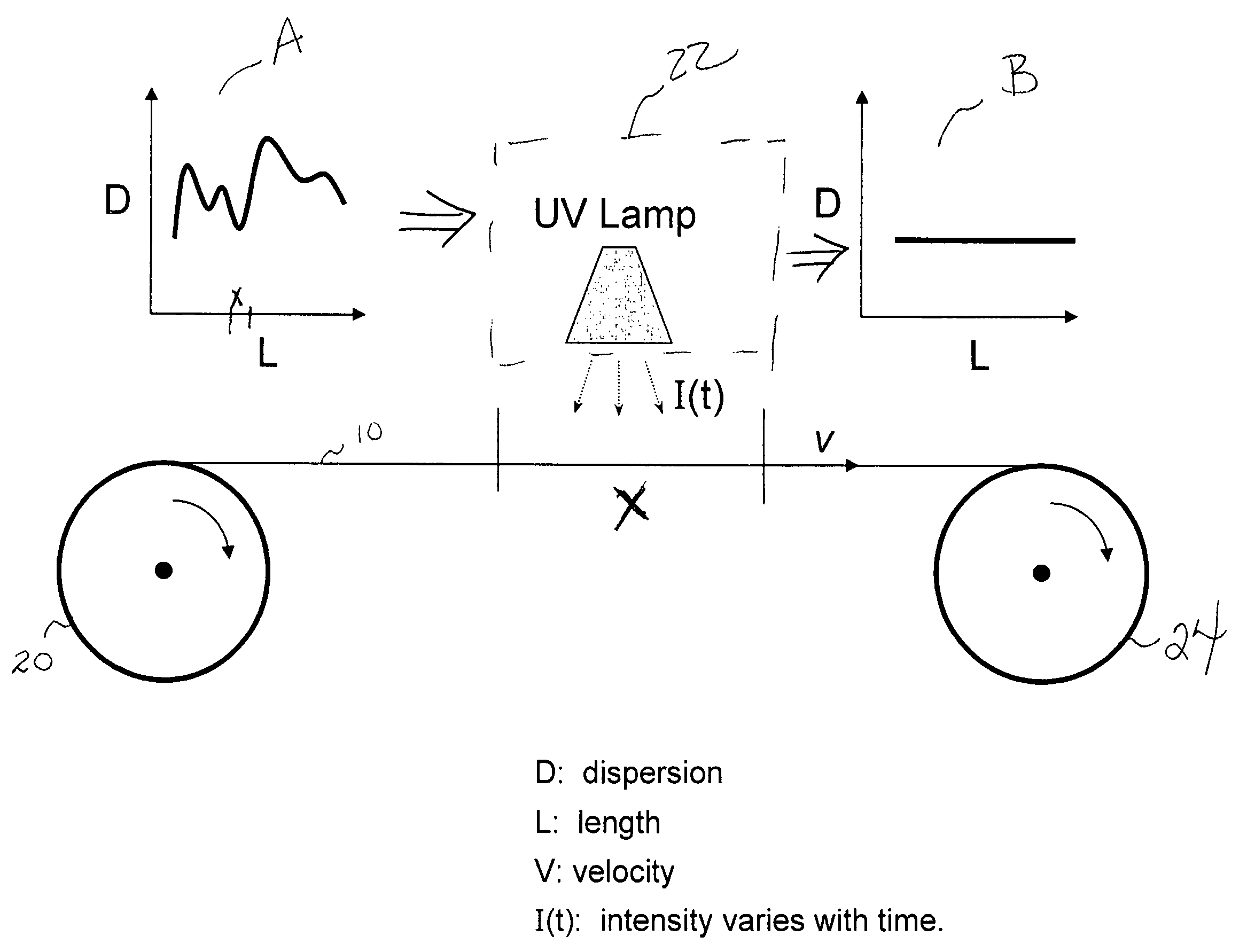
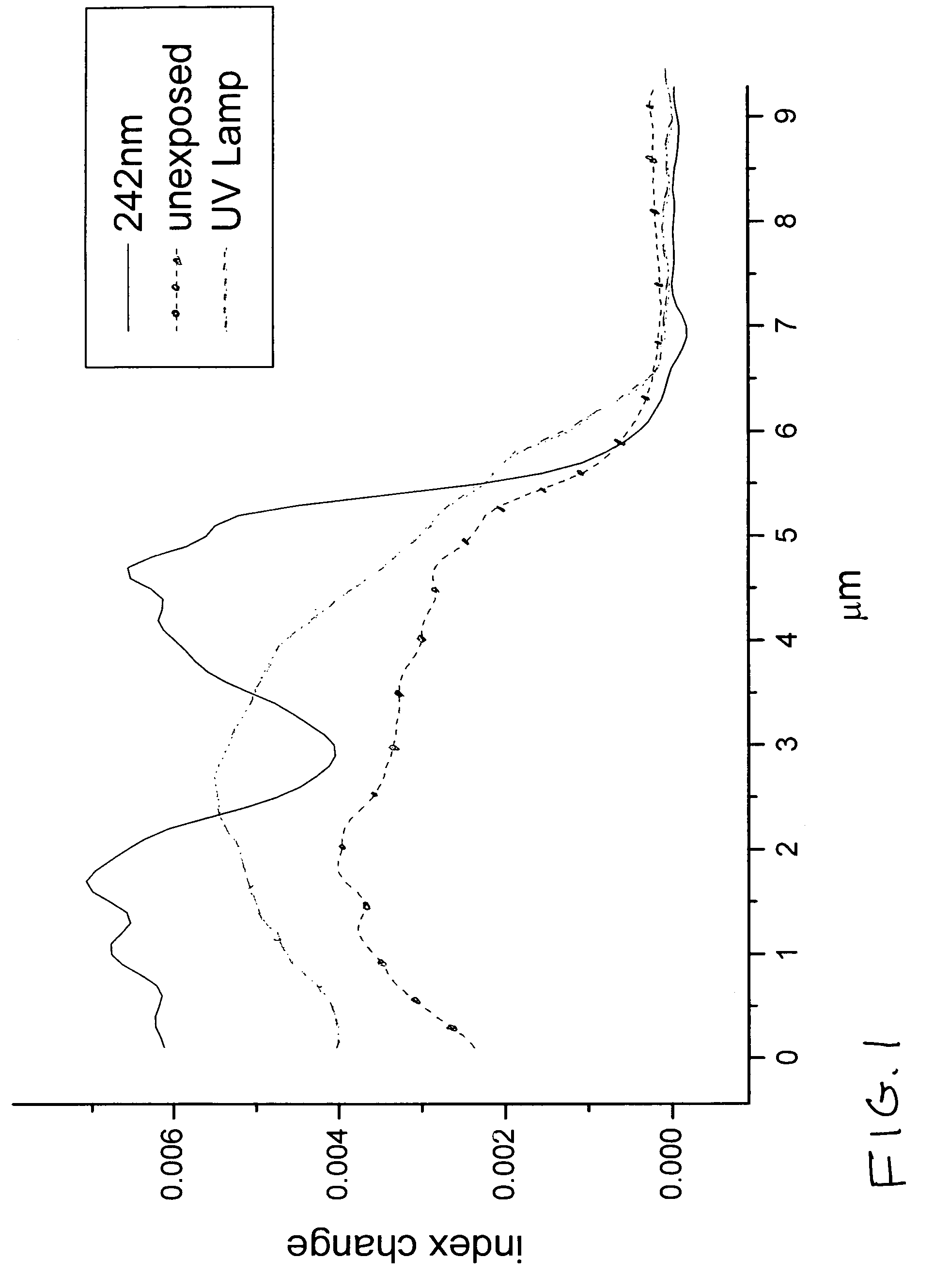
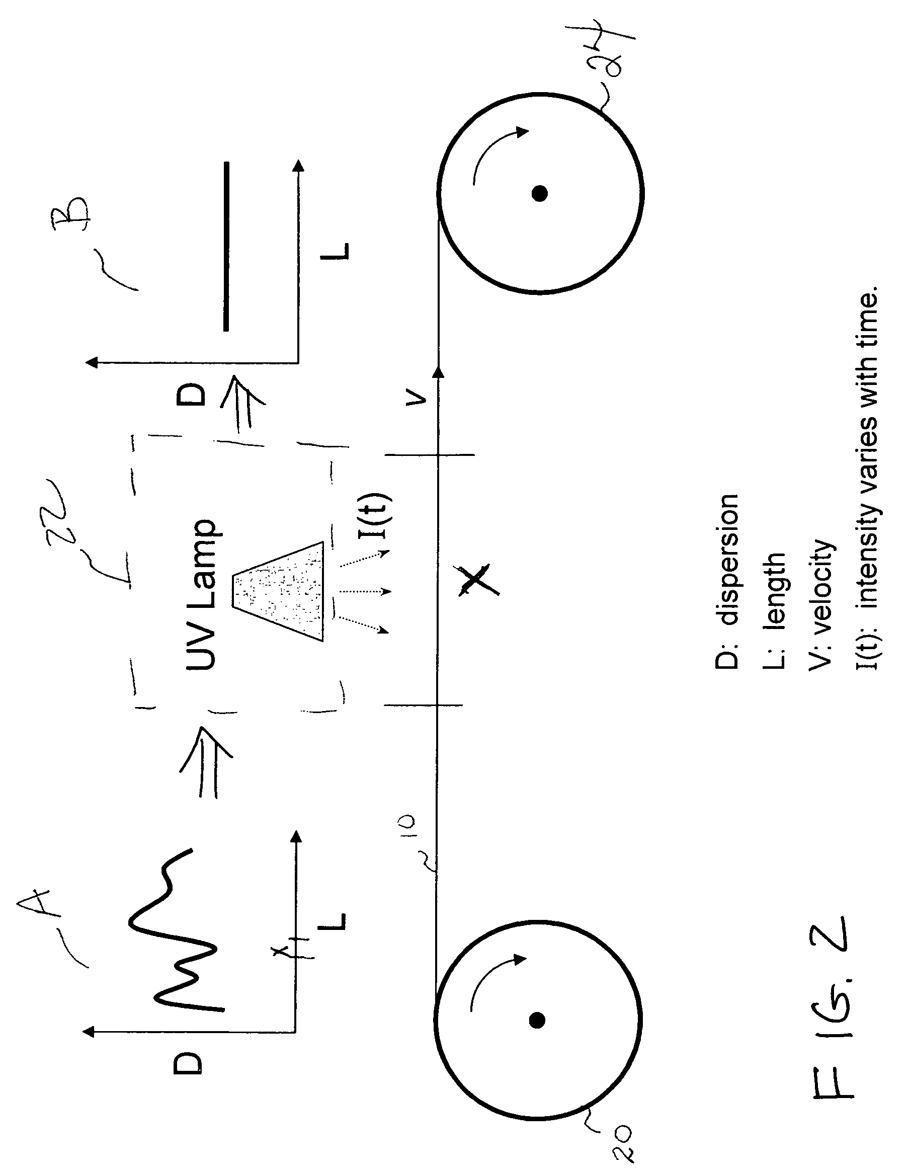
[0025]Previously, techniques such as UV exposure have been used to modify the refractive index of short sections of optical fiber. The ability to “write” gratings into optical fibers with UV radiation has been standard practice (see, for example, U.S. Pat. No. 5,773,486 for a complete description of one exemplary UV-writing process). Recently, UV radiation has been utilized with highly-nonlinear fiber (HNLF) to create four-wave mixing (FWM) or extend continuum generation to provide a supercontinuum source. In the latter case, a UV exposure on the order of 2.5 kJ / cm2 was applied to a deuterium-loaded HNLF to create an index change of 0.005, causing a shift in the zero dispersion wavelength (ZDW) of almost 100 nm.

[0026]In contrast, the length-dependent modifications in optical characteristics performed by the present invention require UV radiation levels which are orders of magnitude less than those required for these prior art applications. Profiles of grating growth in HNLF have sho...


PUM

PropertyMeasurementUnit
wavelengthsaaaaaaaaaa

Abstract

A method of creating optical fiber to exhibit predetermined length-dependent characteristics (e.g., chromatic dispersion, polarization mode dispersion, cutoff wavelength, birefringence) includes the steps of: characterizing the fiber's selected characteristic(s) as a function of length; and performing a “treatment” which modifies the refractive index over the given length to adjust the defined parameter to fall within a defined tolerance window. These steps may be repeated one or more times until the measure of the parameter falls with the defined tolerance limits. The treatment process may include, for example, a low energy actinic radiation exposure, anneal, mechanical strain, DC voltage, plasma application, etc. Indeed, if the treatment process is repeated, a different technique may be used to adjust the refractive index (“different” processes include, for example, modifying the strength / time of a UV exposure, temperatures for annealing, etc.).

Description

TECHNICAL FIELD[0001]The present invention relates to a method of fabricating optical fiber and, more particularly, to a method of modifying an optical fiber's refractive index as a function of length to create predetermined length-dependent characteristics as required for different applications.BACKGROUND OF THE INVENTION[0002]Optical fiber continues to evolve as a transport mechanism in a variety of applications including, but not limited to, communication systems, industrial and environmental sensors, medical imaging and the like. More applications continue to be uncovered daily. When first used in telecommunication applications, the characteristics of a basic silica fiber (in terms of core / cladding dimensions, refractive index profile, etc.) were relatively simple to be controlled using processes such as modified chemical vapor deposition (MCVD) and vapor-assisted deposition (VAD) developed at Bell Laboratories in the 1970's and 80's (see, for example, U.S. Pat. Nos. 4,257,797; ...

Claims


Application Information

Patent Timeline
Patent Type & Authority Patents(United States)
IPC IPC(8): B29D11/00
CPCC03C25/62G02B6/02247
Inventor DIGIOVANNI, DAVID J.NICHOLSON, JEFFREY W.WESTBROOK, PAUL S.YAN, MAN F.
Owner OFS FITEL LLC
Why Eureka
Try Eureka