Frame-shaped MEMS piezoresistive resonator

a piezoresistive resonator and frame-shaped technology, applied in piezoelectric/electrostrictive/magnetostrictive devices, piezoelectric/electrostriction/magnetostriction machines, electrical equipment, etc., can solve problems such as vibration out of plan

Active Publication Date: 2013-11-26
NXP BV
View PDF14 Cites 7 Cited by
  • Summary
  • Abstract
  • Description
  • Claims
  • Application Information

AI Technical Summary

Benefits of technology

[0019]The present invention relates to a MEMS piezoresistive resonator, preferably a silicon resonator, wherein the resonator has the form of a frame, preferably a circular form or polygonal form, such as square, rectangular, hexagonal, octagonal, decagonal, comprising two or more anchors, and one or more electrodes for exciting the resonator, wherein the resistivity of resonator material is at least one first location relatively high and / or wherein the resistivity of resonator material is at least one second location relatively low, a method of operating said MEMS resonator, a method of minimizing energy loss in said MEMS resonator, and a device comprising said resonator.
[0020]Advantages of this device are large readout signal, large electrode area, robustness, suppressed out-of-plane vibration and larger usable linear range. The readout signal is more than 10 times larger than for capacitive readout, typically more than 100 times larger than for capacitive readout, such as more than 500 times larger. The electrode area is in fact virtually not limited, especially when electrodes are placed both at the outer rim and inner rim of the resonator. The robustness, e.g. in terms of stiffness, is very large and allows for very high amplitudes of the resonator. It is noted that the present resonator operates in e.g. elliptic mode shape. Compared to e.g. a dog-bone configuration the out-of-plane vibration is largely suppressed. Compared to e.g. a dog-bone configuration the usable linear range is at least five times higher, e.g. a dog-bone has a linear behavior at Vdc up to about 25V, whereas the present configuration has a linear behavior at Vdc up to about 130V or higher.

Problems solved by technology

It has been found, after thorough research, that the appearance of the out-of-plane vibration in the above prior art devices is mainly due to the fact that most of the designs consist of large or long resonant structure which is hung by only two small anchors, and due to that the anchors are not evenly distributed around the structure.

Method used


Image

  • Frame-shaped MEMS piezoresistive resonator
  • Frame-shaped MEMS piezoresistive resonator
  • Frame-shaped MEMS piezoresistive resonator

Examples


embodiment 1

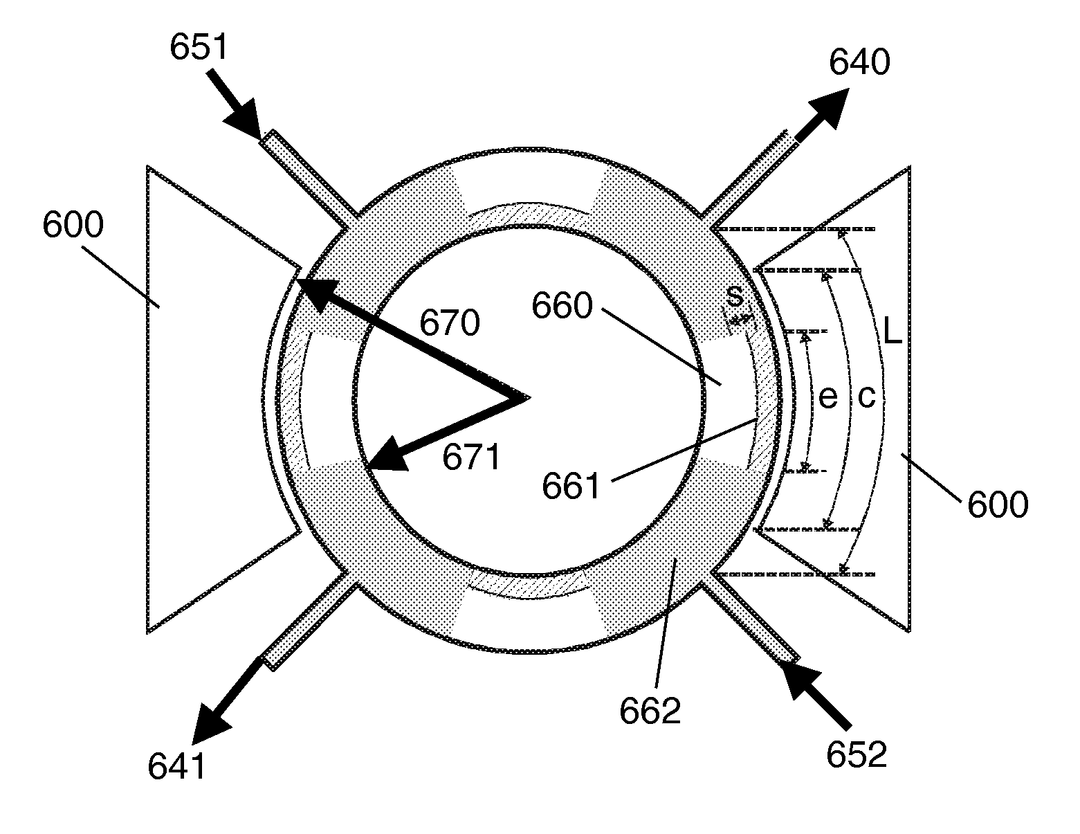
[0085]In a most preferred embodiment, the proposed resonator consists of a ring which is anchored at four symmetrical points, see FIG. 5a. There are two electrodes placing close to the outer rim, at two opposite segments.

[0086]In a second most preferred embodiment, the proposed resonator consists of a rectangle, preferably a square, which is anchored at four symmetrical points, see FIG. 5b.

[0087]In a third most preferred embodiment, the proposed resonator consists of a rectangle, which is anchored at two symmetrical points, see FIG. 5c.

[0088]If a combination of AC and DC excitation voltages is applied on the electrodes, the ring will vibrate in the elliptic mode shape, see FIG. 6, in which the segments of the ring between the anchors alternatively flex inward and outward. The anchors are positions at the nodes of the mode shape at which the structure only slightly rotates, but not significantly displaces. With this arrangement the vibration energy loss through the anchors is minim...

embodiment 2

Readout Configuration

[0121]Because we have 4 anchors and many possibilities to choose the locations of the piezoresistive regions with both negative and positive strain, there can be many possible readout configurations. For instance, in FIG. 10, a Wheatstone bridge configuration is shown. The piezoresistive regions are all located at the outer rim (or alternatively they are all at the inner rim). During any half vibration cycle, the piezoresistive signal alternates from one segment to the next, due to the alternating strain signs, as shown by R↑ and R↓ in the figure. If a DC voltage is applied in between two opposite anchors, the output voltage signal can be obtained from the other two anchors. Due to the Wheatstone bridge configuration, the signal change is doubled, as compared to the normal configuration.

[0122]Different doping types can also be implemented within the same resonant structure. The sign of the piezoresistive gauge factor depends on the dope type: it is negative for ...

embodiment 3

Electrode Configuration

[0123]To maximize the electrode area, thus maximizing the transduction efficiency, four electrodes on all four segments of the ring can be used (FIG. 11). To drive the resonator correctly, AC driving voltage on the other two electrodes (e.g. electrodes 1103 and 1104) should be in anti-phase with the first two electrodes (electrodes 1101 and 1102).

[0124]Even it is not desired, a configuration with only one electrode is also possible.

[0125]Instead of having the electrodes at the outer rim of the structure, the electrodes (1201, 1202 or more electrodes) can also be placed at the inner rim of the structure, for example as illustrated in FIG. 12a.

[0126]Electrodes can also be placed inside and outside the ring, as shown in FIG. 12b. In this configuration all electrodes are connected together (having in-phase electrical voltages). So in a half of an excitation cycle, electrodes 1201 and 1202 pull the west and east segments inwards whereas electrodes 1203 and 1204 pu...


PUM


Abstract

A novel Si MEMS piezoresistive resonator is described. The resonator has a shape of a frame, such as a ring or a polygon frame, which has two or more anchors. Electrodes located at the outer or inner rim of the resonant structure are used to excite the structure electrostatically into resonance with a desired mode shape. One or plurality of locally doped regions on the structure is used for piezoresistive readout of the signal. In the most preferred embodiments, the structure is a ring, which has four anchors, two electrodes and four piezoresistive regions at different segments of the structure. The piezoresistive regions are alternatively located at the outer rim and inner rim of the structure in such a way that the piezoresistive signals of the same sign from different regions can be collected. Advantages of this device are large readout signal, large electrode area, robustness, suppressed out-of-plane vibration and larger usable linear range.

Description

FIELD OF THE INVENTION[0001]The present invention relates to a piezo frame resonator.BACKGROUND OF THE INVENTION[0002]MEMS resonators are being intensively studied in many research groups and some first products have recently been released. This type of device offers a high Q-factor, small size, high level of integration and potentially low cost. These devices are expected to replace bulky quartz crystals in high-precision oscillators and may also be used as RF filters. The oscillators are widely used in time-keeping and frequency reference applications such as RF modules in mobile phones, devices containing blue-tooth modules and other digital and telecommunication devices.[0003]Microelectromechanical systems (MEMS) are the technology of the very small, and merge at the nano-scale into nanoelectromechanical systems (NEMS) and nanotechnology. MEMS are also referred to as micromachines (in Japan), or Micro Systems Technology—MST (in Europe). MEMS are separate and distinct from the hy...

Claims


Application Information

Patent Timeline
Patent Type & Authority Patents(United States)
IPC IPC(8): H01L41/107
CPCH03H9/02259H03H9/2431H03H2009/02307H03H2009/02354H03H2009/02496
Inventor PHAN LE, KIMVAN BEEK, JOZEF T. M.
Owner NXP BV
Why Eureka
Try Eureka