
High-efficiency MEMS micro-vibrational energy harvester and process for manufacturing same

a micro-vibrational, energy harvester technology, applied in the direction of electric generator control, generator/motor, transportation and packaging, etc., can solve the problems of limited life, not well known for wireless applications, and applications that have not developed as quickly as predicted

Inactive Publication Date: 2013-11-26
MCB CLEAN ROOM SOLUTIONS
View PDF26 Cites 18 Cited by
  • Summary
  • Abstract
  • Description
  • Claims
  • Application Information

AI Technical Summary

Benefits of technology

This configuration enables MEMS energy harvesters to respond to low frequencies with increased power output and broader frequency range, eliminating the need for multiple connected harvesters and reducing physical defects, while self-compensating film stresses.

Problems solved by technology

However, due to the limitations described herein, they are not well known for wireless applications.
These applications have not developed as quickly as predicted, in part, because of the difficulty of providing power to the sensors.
Although batteries can be used, they have a limited life and must be replaced periodically.
Since remote sensors are typically placed in inaccessible places (because of the difficulty of running wiring), battery changing can be difficult or impossible.
There is additionally a cost for using batteries which includes labor, the recurring cost of the battery, and disposal, with its attendant environmental concerns.
Microfabricated VEH Devices (μVEHs), however, have their own set of problems.
For MEMS μVEHs, this is difficult.
It is relatively difficult to construct large structures with such thin film fabrication techniques.
One of the primary reasons for such low outputs is the limited stress that can be applied to the piezoelectric element.
A second limitation of the MEMS monomorph architecture is that the mechanical energy that drives the cantilever must be shared between bending the support cantilever and bending the piezoelectric element.
The energy that is required to bend the support does not go into straining the piezoelectric, thereby limiting the amount of voltage that can be developed.
The difficulty with this approach is that in order to respond identically to input acceleration, the cantilevers and proof masses must be identical.
Otherwise, they will have different resonant frequencies or phases and interfere with one another.
Additionally, valuable chip space is lost since it must be used for redundant cantilevers to boost output at a single frequency.
This, however, has its own difficulties.
However, PZT is very difficult to etch.
However, finding etches that are selective between MN and its common electrode material molybdenum (Mo) is also challenging.
Another challenge is that precision is required when building the bimorph to get the numerous film thicknesses correct in order to place the neutral axis correctly.
An issue all the aforementioned MEMS approaches have in common is film stress gradient control.
Unfortunately, however, the thickness of this compensating layer has to be fine tuned to balance out the stack stress.
This can be accomplished, but balancing acts are hard to maintain, as processes and materials possess variability.

Method used


Image

  • High-efficiency MEMS micro-vibrational energy harvester and process for manufacturing same
  • High-efficiency MEMS micro-vibrational energy harvester and process for manufacturing same
  • High-efficiency MEMS micro-vibrational energy harvester and process for manufacturing same

Examples


Embodiment Construction

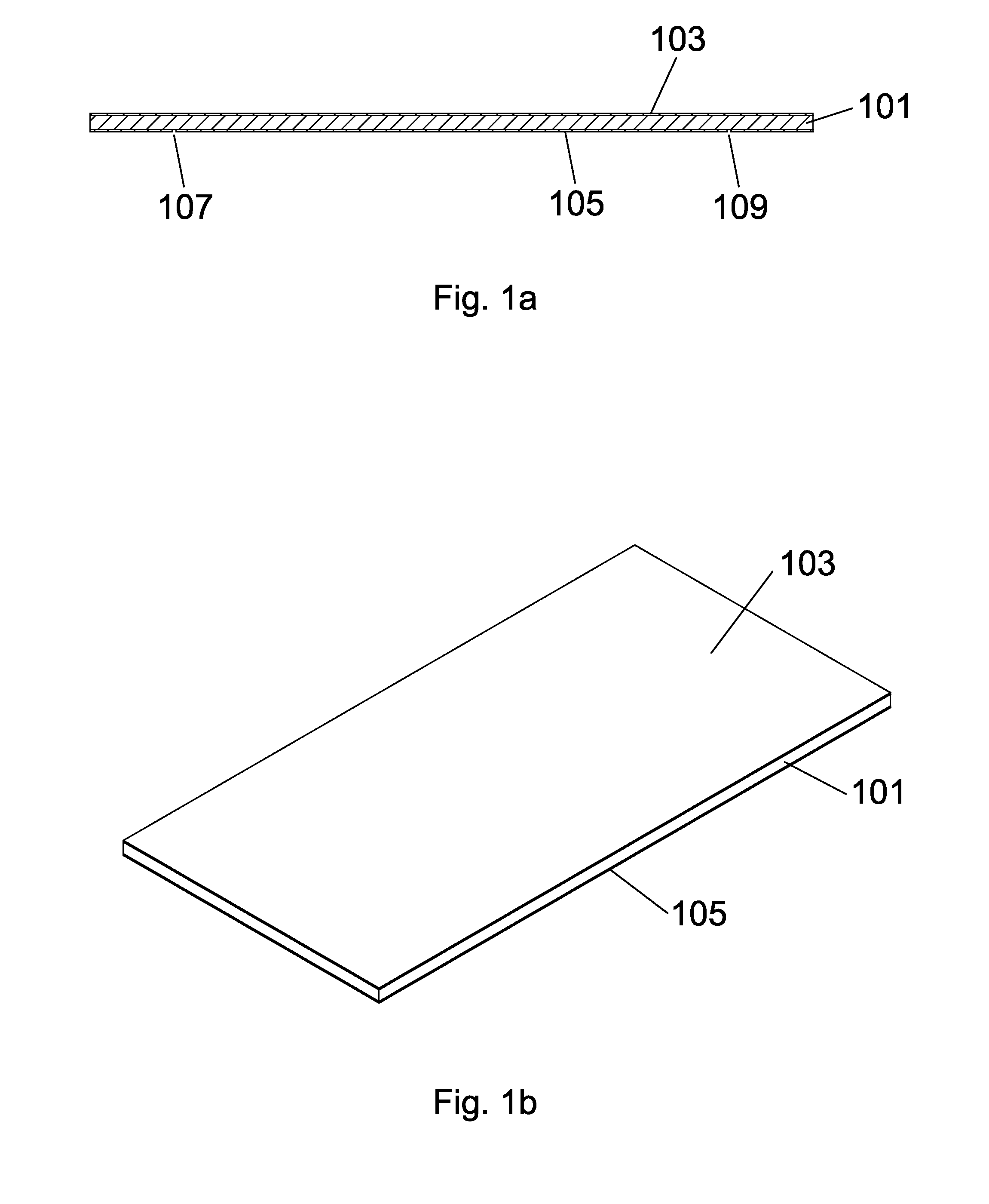
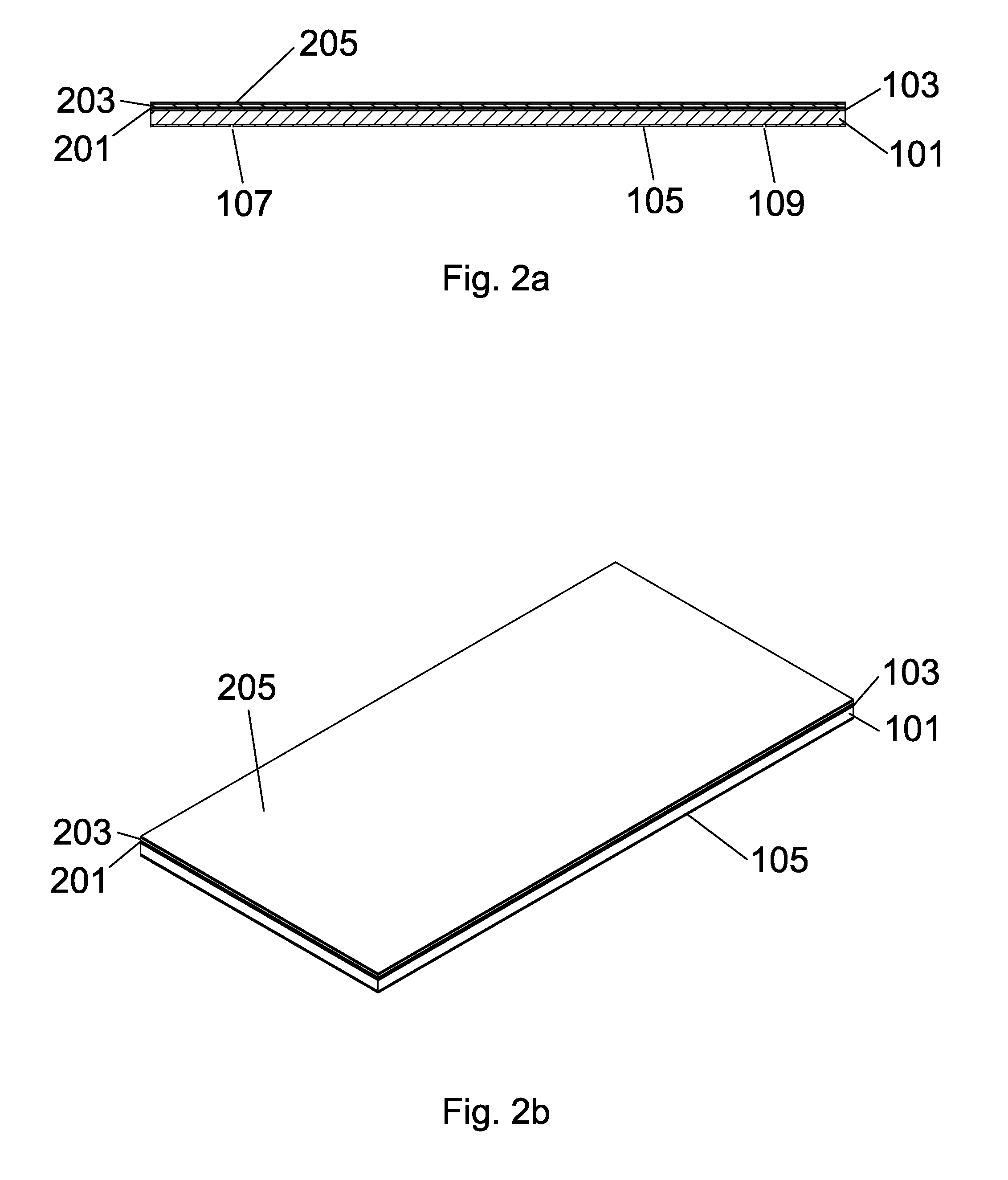
[0059]For a general understanding of the present invention and the various embodiments described or envisioned herein, reference is made to the drawings. In the drawings, like reference numerals have been used throughout to designate identical elements.

Related Terminology

[0060]MEMS: Micro-Electro-Mechanical Systems. MEMS are integrated circuits (ICs) to manufactured using processes and equipment similar to that used in the microelectronics industry. MEMS ICs include mechanical, fluidic, or optical elements in addition to electrical circuits. MEMS ICs are used for applications such as miniature sensors and transducers.[0061]Piezoelectric: A material property for which the application of a force or stress to a piezoelectric sensitive material results in the development of a charge in the material which in turn generates an electric field in the material. The piezoelectric property is a tensor property. The application of a stress along one dimension can result in an electric field bei...


PUM

PropertyMeasurementUnit
pressureaaaaaaaaaa
vibrational frequenciesaaaaaaaaaa
resonant frequenciesaaaaaaaaaa

Abstract

The present invention relates generally to a High Efficiency MEMS Micro-Vibrational Energy Harvester (μVEH) having a thick beam bimorph architecture. The disclosed architecture is capable of producing a voltage of sufficient magnitude such that the requirement to connect a plurality of harvesters in series to produce an adequate voltage magnitude is eliminated.

Description

[0001]This application claims priority to U.S. Patent Application Ser. No. 61 / 308,354 filed Feb. 26, 2010 entitled “High-Efficiency MEMS Micro-Vibrational Energy Harvester And Process For Manufacturing Same” by Robert Mark Boysel of Honeoye Falls, N.Y., U.S.A.BACKGROUND OF THE INVENTION[0002]1. Field of the Invention[0003]The present invention relates generally to energy scavengers and energy harvesters which convert ambient forms of energy into electricity, and more particularly to vibrational energy harvesters that convert environmental mechanical vibrational energy to electrical energy utilizing piezoelectric type materials.[0004]2. Description of the Related Art[0005]One of the most familiar types of energy harvester is the solar cell. Additionally, there are energy harvesters that convert thermal gradients, wind power, water power, and the like into electric power. To take advantage of these types of energy harvesters, environmental contact such as exposure to light, thermal gr...

Claims


Application Information

Patent Timeline
Patent Type & Authority Patents(United States)
IPC IPC(8): H01L41/08H10N30/00H10N30/01H10N30/30
CPCH01L41/1136H02N2/188H01L41/22H10N30/306H10N30/01Y10T29/42
Inventor BOYSEL, ROBERT MARK
Owner MCB CLEAN ROOM SOLUTIONS
Learn More