Fuel rail for high-pressure direct-injection internal combustion engines and method for manufacturing thereof

a technology of internal combustion engines and fuel rails, which is applied in the direction of machines/engines, applications, soldering apparatuses, etc., can solve the problems of poor layout properties, increased production costs, and above-described conventional fuel rails for high-pressure direct-injection internal combustion engines made of aluminum or stainless steel. , to achieve the effect of improving quality, low cost and high sealing property of o-ring seals

Inactive Publication Date: 2013-12-03
USUI KOKUSAI SANGYO KAISHA LTD
View PDF36 Cites 17 Cited by
  • Summary
  • Abstract
  • Description
  • Claims
  • Application Information

AI Technical Summary

Benefits of technology

[0008]The present invention has been made in consideration of the problems that the above described conventional fuel rail for high-pressure direct-injection internal combustion engines, especially, the present invention is directed to provide a high-quality fuel rail for high-pressure direct-injection internal combustion engines, and a method for manufacturing such a fuel rail at low cost. Such a high-quality fuel rail has a structure in which an injector holder, a branch nipple and a fastening bracket are directly attached to a main body of the rail, and has advantages that even if thermal deformation occurs at the time of temporary fitting or brazing when assembling the rail, positional accuracy of the injector holder and the branch nipple and surface roughness of a sealing surface can be assured by finish processing such as cutting work after the brazing, which results in having an excellent sealing property, and that the fuel rail has an excellent inclination accuracy or surface roughness of an abutting surface with a partner member of the fastening bracket, and a seating surface of a bolt or a nut.
[0026]Accordingly, the present invention contributes to quality improvement and reduction of a production cost of a highly-reliable fuel rail for high-pressure direct-injection internal combustion engines, the fuel rail is strong enough to withstand an injection pressure of between 150-250 MPa in a compression-ignition engine, and an injection pressure of between 10-40 MPa in a spark-ignition engine.

Problems solved by technology

The above described conventional fuel rails for high-pressure direct-injection internal combustion engines made of aluminum or stainless steel, however, has problems as described below.
In the case of a fuel rail for direct-injection internal combustion engines made of aluminum, there are problems that it cannot be used for the diesel engine in which injection pressure reaches 150-250 MPa because its materials strength is low, and moreover, even if the fuel rail is for gasoline engines, the fuel rail has poor layout property because it is necessary to increase in wall-thickness of the rail so as to withstand high fuel pressure (injection pressure); and that a production cost goes up since it is necessary for its contact surface with fuel to be subjected to special surface treatment because the aluminum fuel rail is sensitive to alcohol and corrosive fuel.
However, there are drawbacks in the fuel rail that positional accuracy at a connection of a fuel injector (injection nozzle) holder is bad which cause a fuel leakage problem, since the fuel rail is assembled by brazing, and moreover a position correction is difficult due to the high strength.
Particularly in a fuel rail for diesel engines, it is totally impossible to correct a position since the wall thickness of the rail is thick and moreover, it might result in worsening of sealing property since the brazing filler metal may hang at a joint of a seal ring of the injector holder connection and then surface roughness of a sealing surface is degraded.
Accordingly, there was a risk that the rail might similarly thermally-deformed.

Method used


Image

  • Fuel rail for high-pressure direct-injection internal combustion engines and method for manufacturing thereof
  • Fuel rail for high-pressure direct-injection internal combustion engines and method for manufacturing thereof
  • Fuel rail for high-pressure direct-injection internal combustion engines and method for manufacturing thereof

Examples


Embodiment Construction

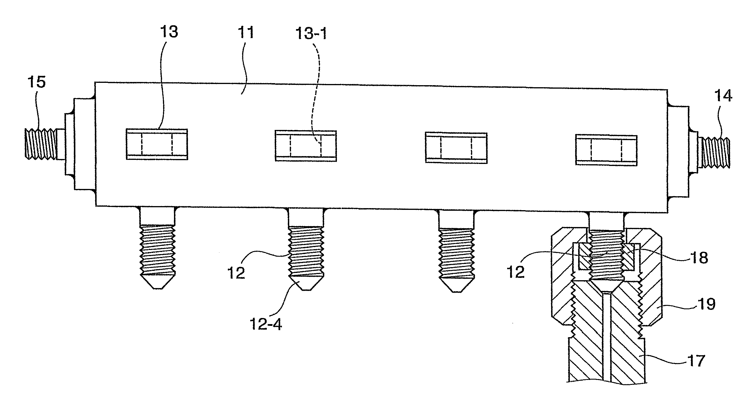
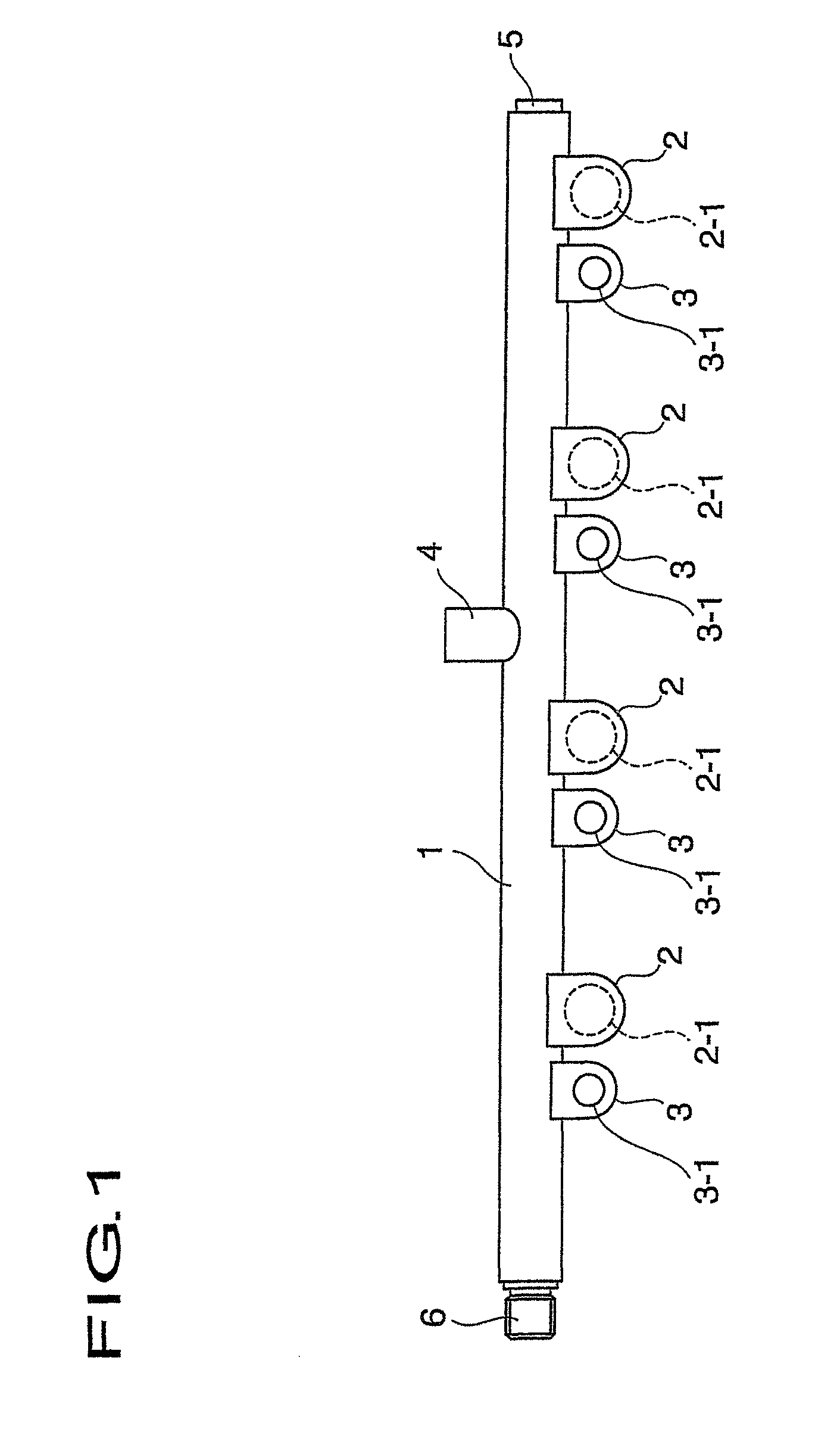
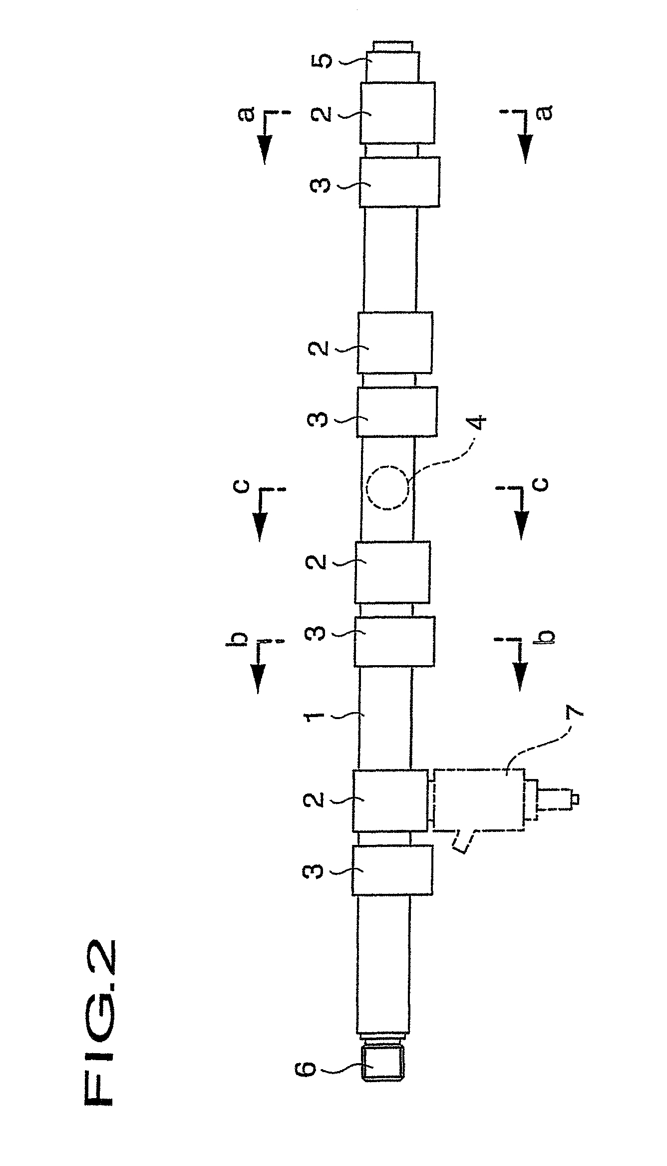
[0041]FIG. 1 is a plane view showing one embodiment of a fuel rail for high-pressure direct-injection internal combustion engines of a spark-ignition type according to the present invention; FIG. 2 is a front view of the fuel rail for high-pressure direct-injection internal combustion engines of a spark-ignition type according to the present invention; FIG. 3A is a cross sectional view of each part of the fuel rail for high-pressure direct-injection internal combustion engines of a spark-ignition type according to the present invention, in particular, an enlarged cross-sectional view cut along an a-a line on FIG. 2; FIG. 3B is a cross sectional view of each part of the fuel rail for high-pressure direct-injection internal combustion engines of a spark-ignition type according to the present invention, in particular, an enlarged cross-sectional view cut along a b-b line on FIG. 2; FIG. 3C is a cross sectional view of each part of the fuel rail for high-pressure direct-injection intern...


PUM

PropertyMeasurementUnit
injection pressureaaaaaaaaaa
thicknessaaaaaaaaaa

Abstract

A fuel rail for high-pressure direct-injection internal combustion engines has an injector holder and a fastening bracket directly attached to a main body of the fuel rail. Thermal deformation may occur at the time of temporary fitting or brazing when assembling the rail. However, positional accuracy of the injector holder can be assured, which results in having an excellent sealing property. Components of the fuel rail for direct-injection internal combustion engines are made of steel or stainless steel, and the components are joined reciprocally by brazing. The components joined by brazing are finished by cutting work and / or burnishing processing after the brazing step.

Description

BACKGROUND OF THE INVENTION[0001]1. Field of the Invention[0002]The present invention relates to a fuel rail (a delivery pipe) for supplying high-pressure fuel, which is supplied from fuel booster pumps of such as electronic fuel injection-type automobile engines, through a fuel injector (an injection nozzle) directly injecting into an engine cylinder. More specifically, the present invention relates to a fuel rail for high-pressure direct-injection internal combustion engines using a compression-ignition method or a spark-ignition method in a type for directly supplying fuel from a rail to an injector, and the manufacturing method of the fuel rail.[0003]2. Description of the Related Art[0004]As a fuel rail for direct-injection internal-combustion engines, there is a fuel rail for the gasoline engines in which main fuel is gasoline, and a fuel rail for the diesel engines in which main fuel is light oil. For example, for a fuel rail for direct-injection gasoline engines, fuel rails a...

Claims


Application Information

Patent Timeline
Patent Type & Authority Patents(United States)
IPC IPC(8): F02M55/02
CPCF02M55/025F02M61/168F02M63/0275B23K1/0008B23K1/19B23K1/20B23K2101/006B23K2101/06B23K2103/04B23K2103/06
Inventor NISHIZAWA, HIROYUKINISHIHARA, HARUOUSUI, SHOICHIROHAYASHI, KOICHITSUCHIYA, HIKARI
Owner USUI KOKUSAI SANGYO KAISHA LTD
Why Eureka
Try Eureka