In-wheel motor drive device
a technology of in-wheel motors and drives, which is applied in the direction of electric devices, electric propulsion mountings, brake discs, etc., can solve the problems of increasing the affecting vehicle design, and increasing the overall radial length of the overall in-wheel motor drive device, so as to increase the axial length of the device and increase the cost
- Summary
- Abstract
- Description
- Claims
- Application Information
AI Technical Summary
Benefits of technology
Problems solved by technology
Method used
Image
Examples
first embodiment
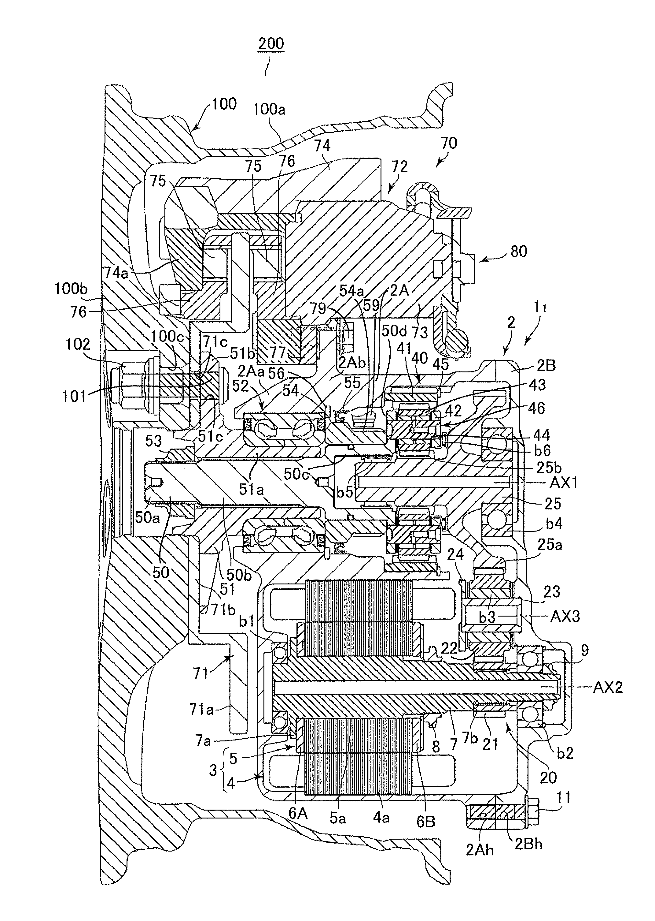
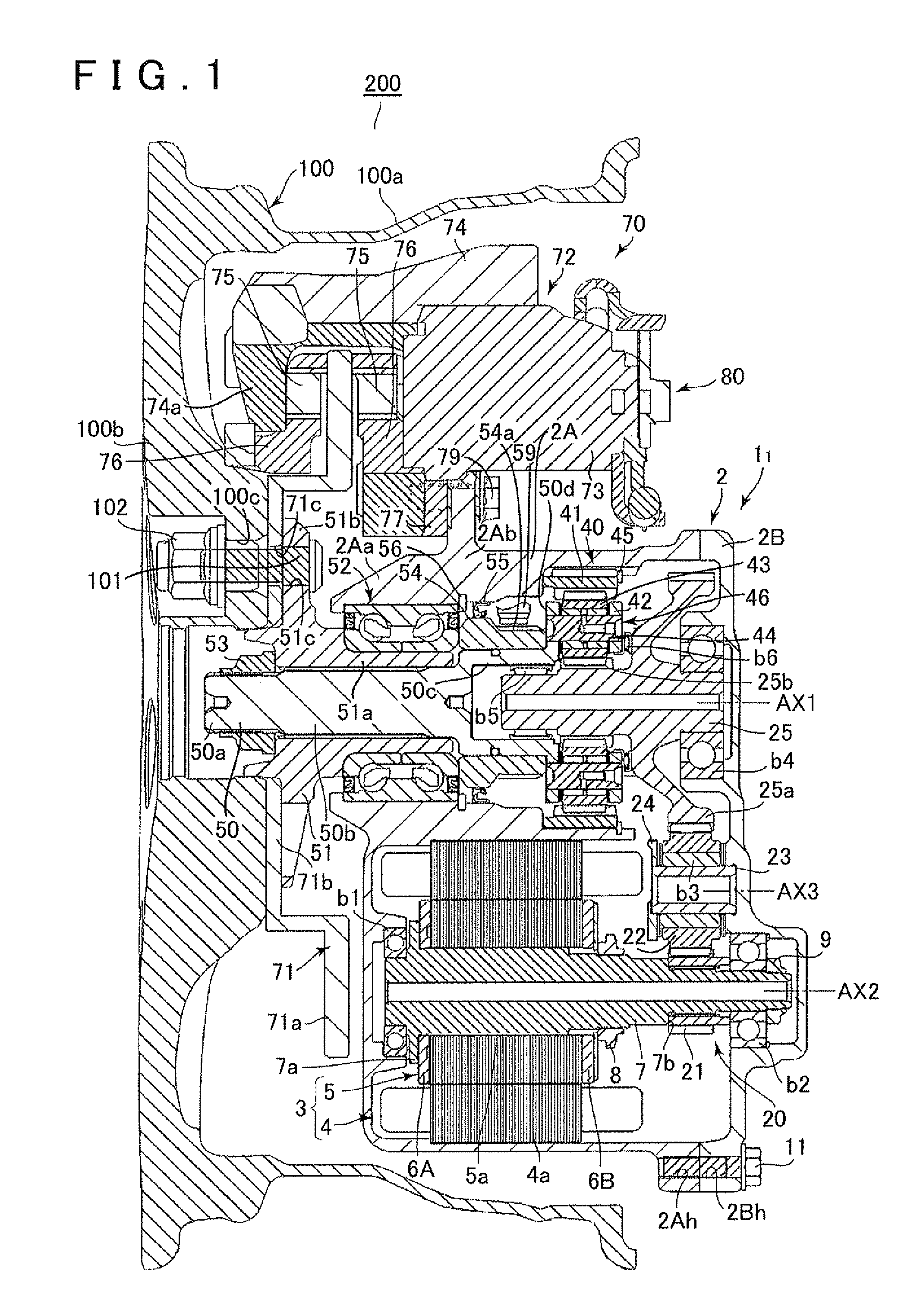
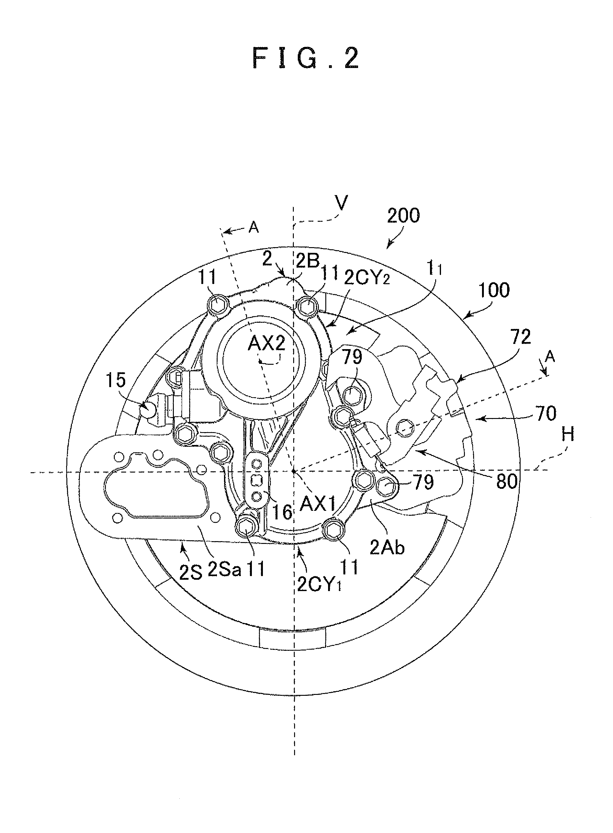
[0041]A first embodiment of the present invention will be described below with reference to FIGS. 1 to 5. First, an in-wheel motor drive device according to the present invention, and the structure of a vehicle wheel provided with the in-wheel motor drive device will be described with reference to FIGS. 1 and 2. Note that an in-wheel motor drive device 11 of the present embodiment is used as a drive device that is attached to inside a wheel of a rear vehicle wheel of a front-wheel-drive hybrid vehicle, and changes the vehicle to a four-wheel-drive mode. In addition to this, the in-wheel motor drive device 11 of the present embodiment may also be used, for example, as a drive device for an electric vehicle, a drive device for a series type of hybrid vehicle, or a drive device that is attached to inside a wheel of a front vehicle wheel of a rear-wheel-drive hybrid vehicle and changes the vehicle to a four-wheel-drive mode.
[0042]As shown in FIG. 1, the in-wheel motor drive device 11 is...
second embodiment
[0083]A second embodiment that partially modifies the first embodiment described above will be explained next with reference to FIGS. 6 to 9. Note that, in the description of the second embodiment, like reference symbols are used for parts identical to those of the first embodiment and such parts are not described further here.
[0084]The second embodiment has a configuration in which the attachment position of the suspension device 90 is modified compared to the first embodiment described above, and the output shaft 50 is directly supported by the suspension device 90 without the intervention of the case 2 of an in-wheel motor drive device 12. The joining portion 95 of the hub arm 92 of the suspension device 90 is interposed between the wheel hub 51 and the main case 2A, which shortens the main case 2A in the axial direction, and also shortens the motor 3 in the axial direction as a consequence. Thus, the motor 3 can be changed to a small induction motor with a small output.
[0085]Mor...
third embodiment
[0093]A third embodiment that partially modifies the first embodiment described above will be explained next with reference to FIG. 10. Note that, in the description of the third embodiment, like reference symbols are used for parts identical to those of the first embodiment and such parts are not described further here.
[0094]In the third embodiment, compared to the first embodiment described above, the motor 3 is changed from an induction motor to an IPM synchronous motor (permanent magnet embedded type motor). Accompanying the modification of the motor 3, in order to perform a control that detects the precise rotation position of the motor 3, a resolver device 30 is installed that detects the rotation position of the rotor shaft 7.
[0095]More specifically, the resolver device 30 of an in-wheel motor drive device 13 is configured to include a resolver rotor 32 that is fastened by a nut 33 that is more toward the proximal end portion of the rotor shaft 7 (the end portion on the right...
PUM
 Abstract
Description
Claims
Application Information
 - R&D
- Intellectual Property
- Life Sciences
- Materials
- Tech Scout
- Unparalleled Data Quality
- Higher Quality Content
- 60% Fewer Hallucinations
Browse by: Latest US Patents, China's latest patents, Technical Efficacy Thesaurus, Application Domain, Technology Topic, Popular Technical Reports.
© 2025 PatSnap. All rights reserved.Legal|Privacy policy|Modern Slavery Act Transparency Statement|Sitemap|About US| Contact US: help@patsnap.com


