Wireless transmit and receive MRI coils

a wireless, mri coil technology, applied in the field of magnetic resonance arts, can solve the problems of reducing patient throughput, subject discomfort, inconvenience during setup, etc., and achieve the effects of reducing the number of cables running, reducing the number of cables, and improving patient safety

Active Publication Date: 2013-12-03
KONINKLIJKE PHILIPS ELECTRONICS NV
View PDF15 Cites 10 Cited by
  • Summary
  • Abstract
  • Description
  • Claims
  • Application Information

AI Technical Summary

Benefits of technology

[0010]Another advantage resides in simplified set-up procedures and improved patient throughput.

Problems solved by technology

The cables leading to and from the transmit and receive coils have numerous drawbacks such as subject discomfort, inconvenience during setup, and reducing patient throughput.
Moreover, the RF fields could induce currents in these cables which could burn or injure the subject, damage electronic components on the transmit or receive coils, reduce image quality, and the like.
Receive coils have very modest power requirements for preamplifiers, analog to digital converters, and other relatively low power consuming electronics.

Method used


Image

  • Wireless transmit and receive MRI coils
  • Wireless transmit and receive MRI coils
  • Wireless transmit and receive MRI coils

Examples


Embodiment Construction

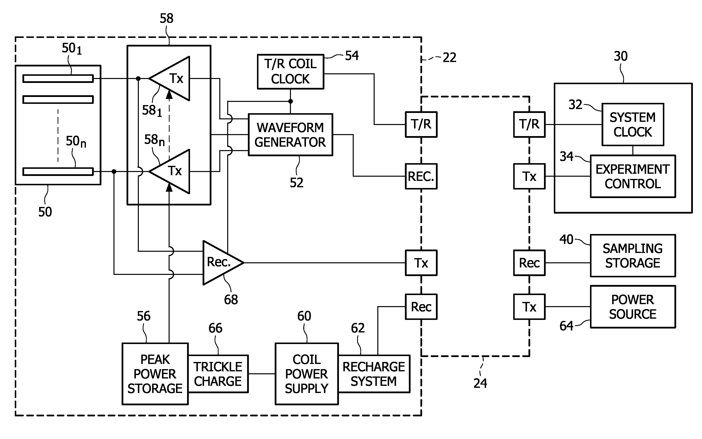
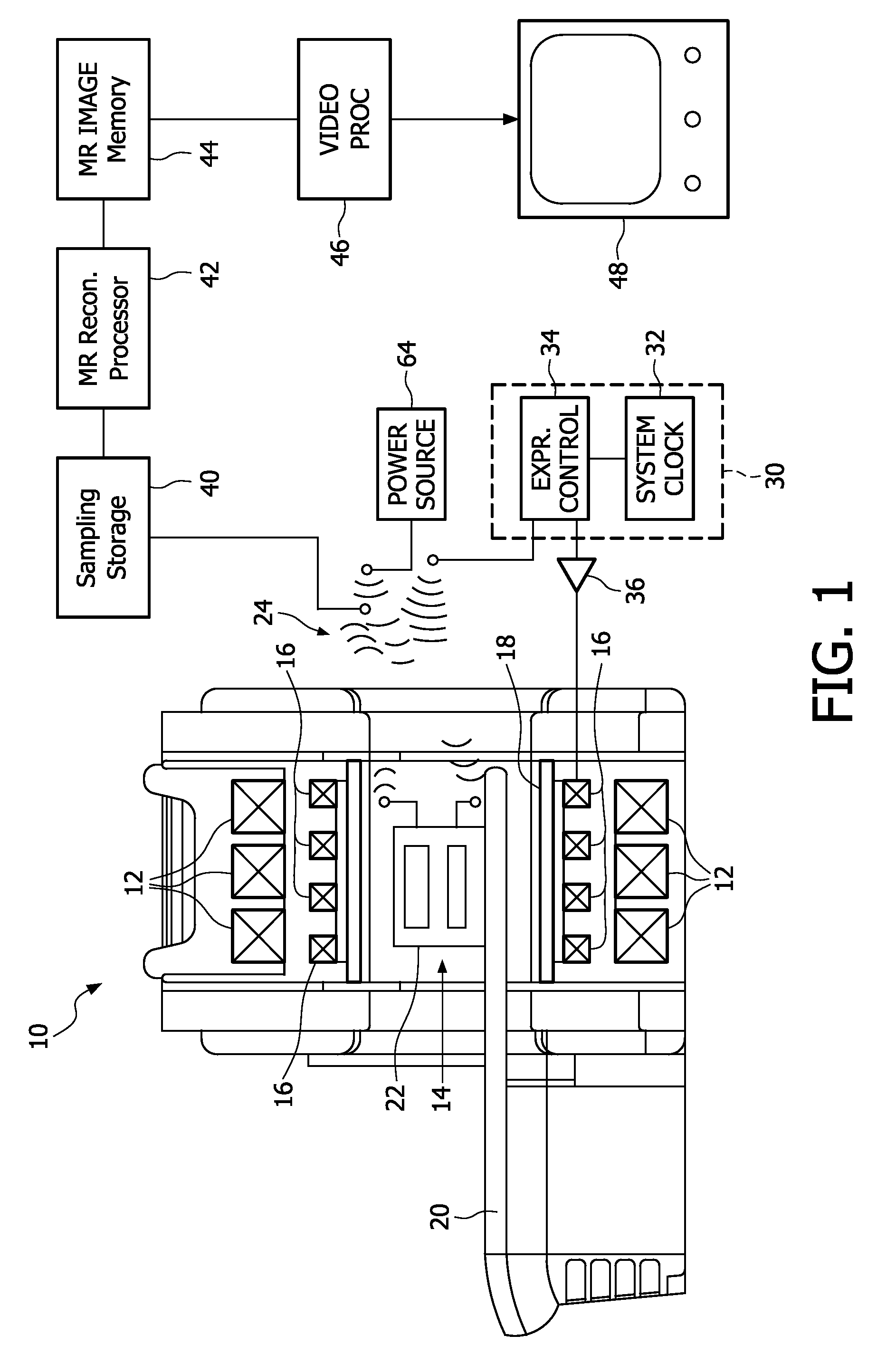
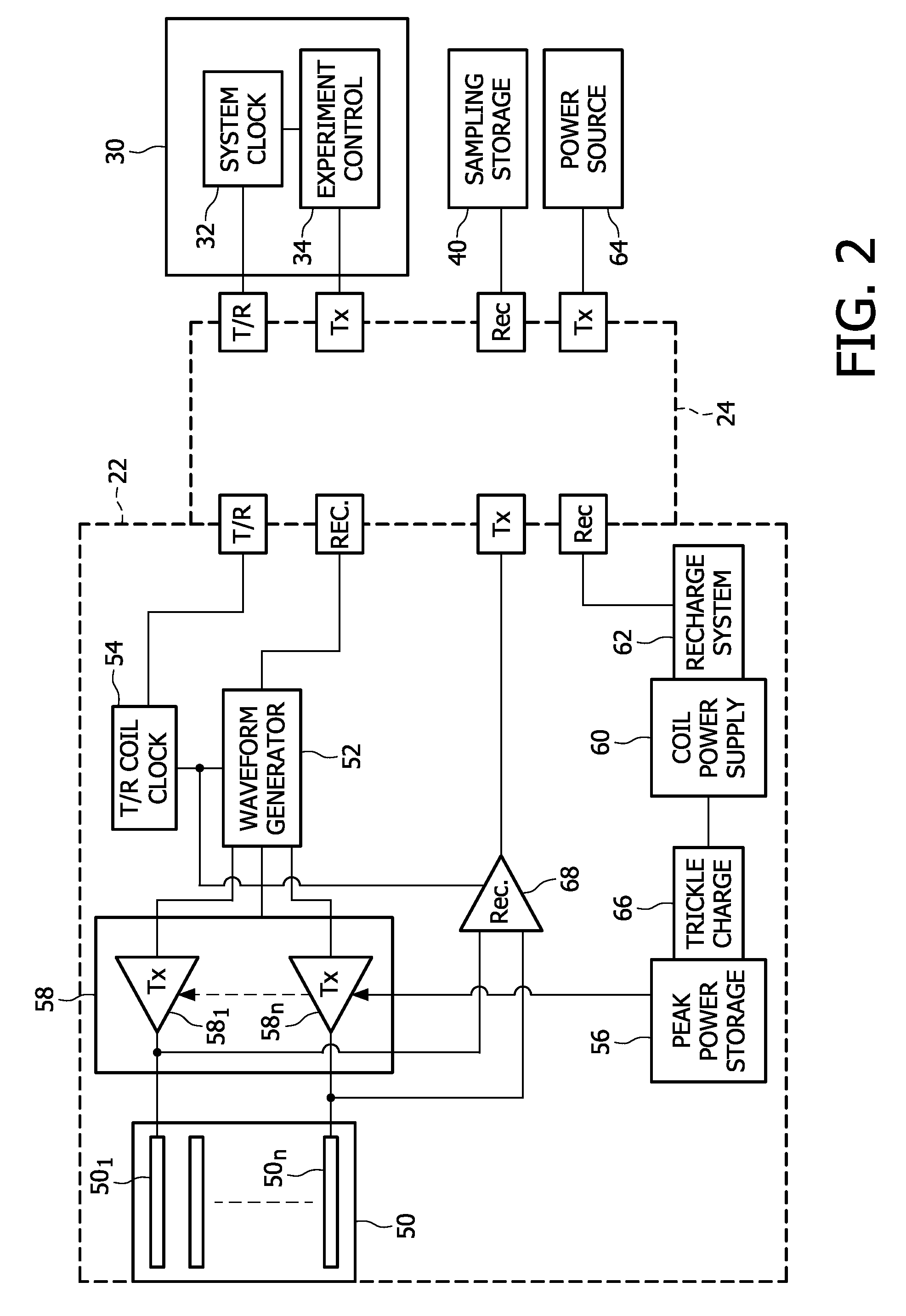
[0016]With reference to FIG. 1, a magnetic resonance imaging system 10 includes a main magnet 12, such as a superconducting magnet, which generates a main or B0 magnetic field through an examination region 14. Although the examination region is illustrated as a bore, open magnet systems, C magnet systems, four post magnet systems, and the like are also contemplated. Gradient magnetic field coils 16 generate magnetic field gradients or gradient pulses across the examination region, typically along three orthogonal directions. Optionally, a whole-body RF coil 18 transmits RF pulses into the examination region 14 and receives magnetic resonance RF signals from the examination region.

[0017]A subject support or pallet 20 selectively moves a subject (not illustrated) into and out of the examination region 14. A local coil 22, a head coil in the illustrated embodiment, is positioned in the examination region in close proximity to the subject. Various local coils, such as a head coil, neck ...


PUM


Abstract

A magnetic resonance system includes a wireless local coil which functions as a transmit only or a transmit and receive coil. The local coil includes an RF coil with a plurality of coil elements. A corresponding number of transmit amplifiers apply RF signals to the RF coil elements to transmit an RF signal. A peak power supply provides electrical power to the transmit amplifiers to transmit relatively high power RF pulses. A trickle charging device recharges the peak power supply between RF pulses front a local coil power supply. A power transfer device wirelessly transfers power to a coil power supply recharging device which recharges the local coil power supply.

Description

FIELD OF THE INVENTION[0001]The present application relates to the magnetic resonance arts. It finds particular application in conjunction with diagnostic imaging on subjects and will be described with particular reference thereto. However, it is to be appreciated, that the concepts described below will also have other applications such as magnetic resonance spectroscopy, preclinical imaging, and the like.BACKGROUND OF THE INVENTION[0002]In magnetic resonance imaging, the patient is placed in a main magnetic field, also called B0 magnetic field. High power radiofrequency signals are transmitted into the patient to excite dipoles in the subject to resonate and to manipulate selected dipoles. Low power signals from the resonating dipoles are received and processed. In magnetic resonance imaging, magnetic field gradients are applied across the imaged region to encode spatial position in the resonance, e.g. by phase or frequency encoding.[0003]In many applications, it is advantageous to...

Claims


Application Information

Patent Timeline
Patent Type & Authority Patents(United States)
IPC IPC(8): G01V3/00G01R33/36
CPCG01R33/3614G01R33/3692A61B5/055G01R33/36G01R33/3607G01R33/3621G01R33/385
Inventor SAES, MARC PAULHELVOORT, MARINUS JOHANNES ADRIANUS MARIA VAN
Owner KONINKLIJKE PHILIPS ELECTRONICS NV
Why Eureka
Try Eureka