Non-destructive thickness measurement systems and methods

a thickness measurement and non-destructive technology, applied in the direction of mechanical measuring arrangements, instruments, using mechanical means, etc., can solve the problems of inability to provide inability to monitor the uniformity of the high-temperature pipe, and inherent delay in providing feedback to the casting system

Active Publication Date: 2013-12-03
US PIPE & FOUNDRY
View PDF13 Cites 2 Cited by
  • Summary
  • Abstract
  • Description
  • Claims
  • Application Information

AI Technical Summary

Problems solved by technology

A common obstacle faced by pipe manufacturers is the monitoring of the uniformity of pipe wall thickness during the manufacturing process.
Although this technique can be useful in measuring pipe wall thickness when the pipe is at a relatively low temperature, high-temperature pipes are not typically measured using the time-of-flight method due to the inability of typical coupling mediums such as oil, water, and glycerin to withstand the high surface temperatures of the pipe walls.
Because this technique requires cooling in order to measure pipe thickness in-process, there is an inherent delay in providing feedback to the casting system.
Further, cooling the pipe for thickness measurement would require greater energy to reheat the pipe during the annealing process.

Method used


Image

  • Non-destructive thickness measurement systems and methods
  • Non-destructive thickness measurement systems and methods
  • Non-destructive thickness measurement systems and methods

Examples


example

[0057]The following non-limiting example illustrates various aspects of some embodiments of the present invention.

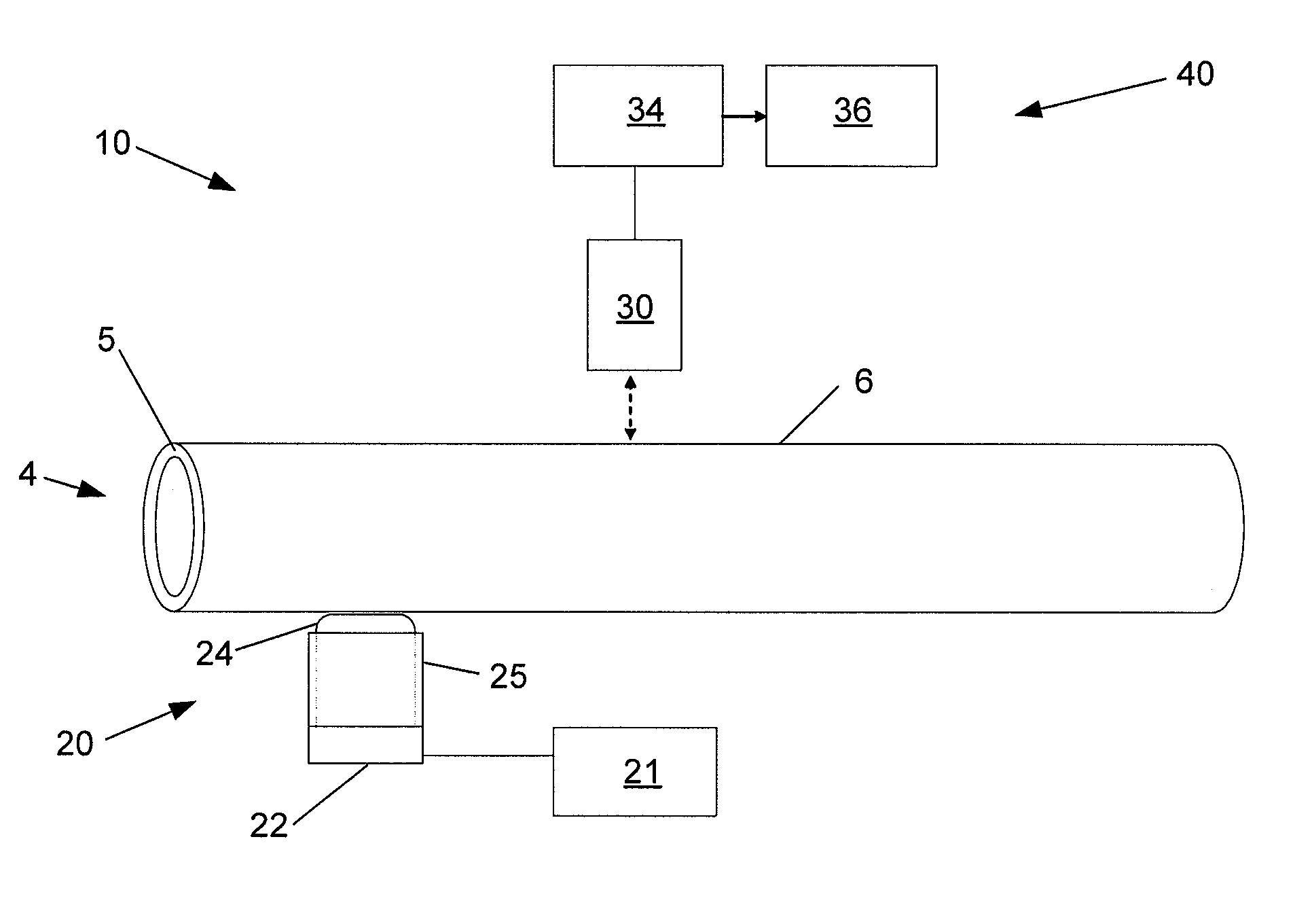
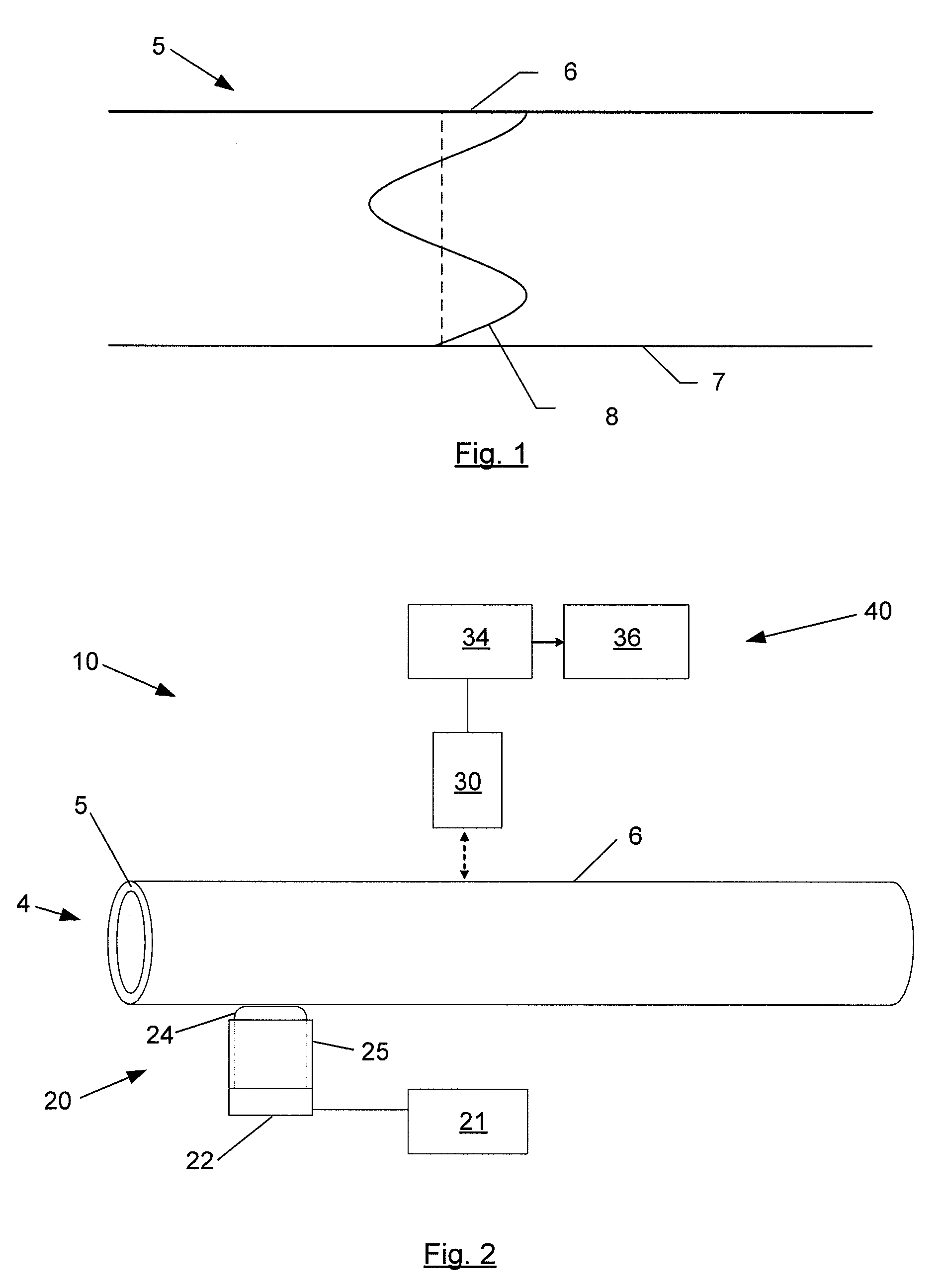
[0058]FIGS. 4-6 illustrate data collected during a test of an annealed 6 inch ductile iron pipe at ambient temperature using an embodiment of the present invention. The desired thickness for the 6 inch pipe is approximately 0.35 inches. A vibration was applied to the pipe using a first piezoelectric transducer operating through a couplant. The reaction of the pipe was monitored using a second piezoelectric transducer.

[0059]FIG. 4 illustrates the white noise signal generated by a signal generator21 in that trial. As can be seen, the white noise includes signal components of various frequencies with all of the frequencies having substantially the same power. As illustrated, the frequency range for this pipe was 0 to 2 MHz.

[0060]The white noise generated by the signal generator 21 was communicated to the first piezoelectric transducer, which applied a vibration into the pip...


PUM


Abstract

The present invention generally relates to improved non-destructive thickness measurement systems and methods. Embodiments of the present invention utilize quarter wave resonant frequency to measure the thickness of high-temperature pipe walls. In one embodiment, an improved non-destructive thickness measurement system is provided that utilizes Gaussian white noise to produce maximum mechanical resonance in the pipe wall and laser vibrometers to detect the pipe wall's maximum displacement.

Description

FIELD OF THE INVENTION[0001]The present invention relates to systems and methods for evaluating attributes of an item. More particularly, embodiments of the present invention use non-destructive techniques to measure the thickness of items by applying vibrations to the item and monitoring the results.BACKGROUND OF THE INVENTION[0002]A common obstacle faced by pipe manufacturers is the monitoring of the uniformity of pipe wall thickness during the manufacturing process. Ductile iron pipe is centrifugally cast by pouring molten iron down a U-shaped trough into an externally water-cooled rotating steel mold. The casting machine traverses the length of the trough as molten iron fills the bell cavity and body of the mold. This casting method is known as the deLavaud process. When the pipe is extracted from the mold, its temperature is approximately 1000° F. Due to the brittle nature of the pipe at this point in the manufacturing process, it must be annealed. In the annealing cycle, the p...

Claims


Application Information

Patent Timeline
Patent Type & Authority Patents(United States)
IPC IPC(8): G01B17/02
CPCG01B17/02
Inventor WATTS, KENNETH J.
Owner US PIPE & FOUNDRY
Why Eureka
Try Eureka