System to cold compress an air stream using natural gas refrigeration

a technology of cold compression and air stream, which is applied in refrigeration, liquid storage, lighting and heating apparatus, etc., can solve the problems of potentially explosive mixtures of oxygen and natural gas, unbalance justified in the use of anything colder than ambient temperature cooling water, etc., and achieve the effect of reducing the possibility of natural gas leaking into the air stream

Inactive Publication Date: 2013-12-10
AIR PROD & CHEM INC
View PDF33 Cites 24 Cited by
  • Summary
  • Abstract
  • Description
  • Claims
  • Application Information

AI Technical Summary

Benefits of technology

[0013]The present invention is a process for the compression of an air stream in multiple stages that uses refrigeration derived from liquefied and / or cold natural gas for cooling the air stream to a sub-ambient temperature between at least two consecutive stages. In order to reduce the possibility of natural gas leaking into the air stream, an intermediate cooling medium (“ICM”) is used to transfer the refrigeration from the natural gas to the inter-stage air stream. In one embodiment of the present invention, the compressed air stream is fed to a cryogenic air separation unit (“ASU”) that includes an LNG-based liquefier unit which is synergistically integrated into the process by using a cold natural gas stream withdrawn from the liquefier unit as the natural gas stream used to cool the ICM.

Problems solved by technology

Typically, this balance does not justify the use of anything colder than ambient temperature cooling water.
In particular, such a leak would permit natural gas to enter the distillation column along with the air stream where the natural gas will tend to collect with the oxygen produced in the distillation column and thus create potentially explosive mixtures of oxygen and natural gas.
It needs to be clearly noted however that Ogata and Ward do not teach to use the cooled ICM to advantageously cool the air stream between its stages of cold compression.

Method used


Image

  • System to cold compress an air stream using natural gas refrigeration
  • System to cold compress an air stream using natural gas refrigeration
  • System to cold compress an air stream using natural gas refrigeration

Examples


example

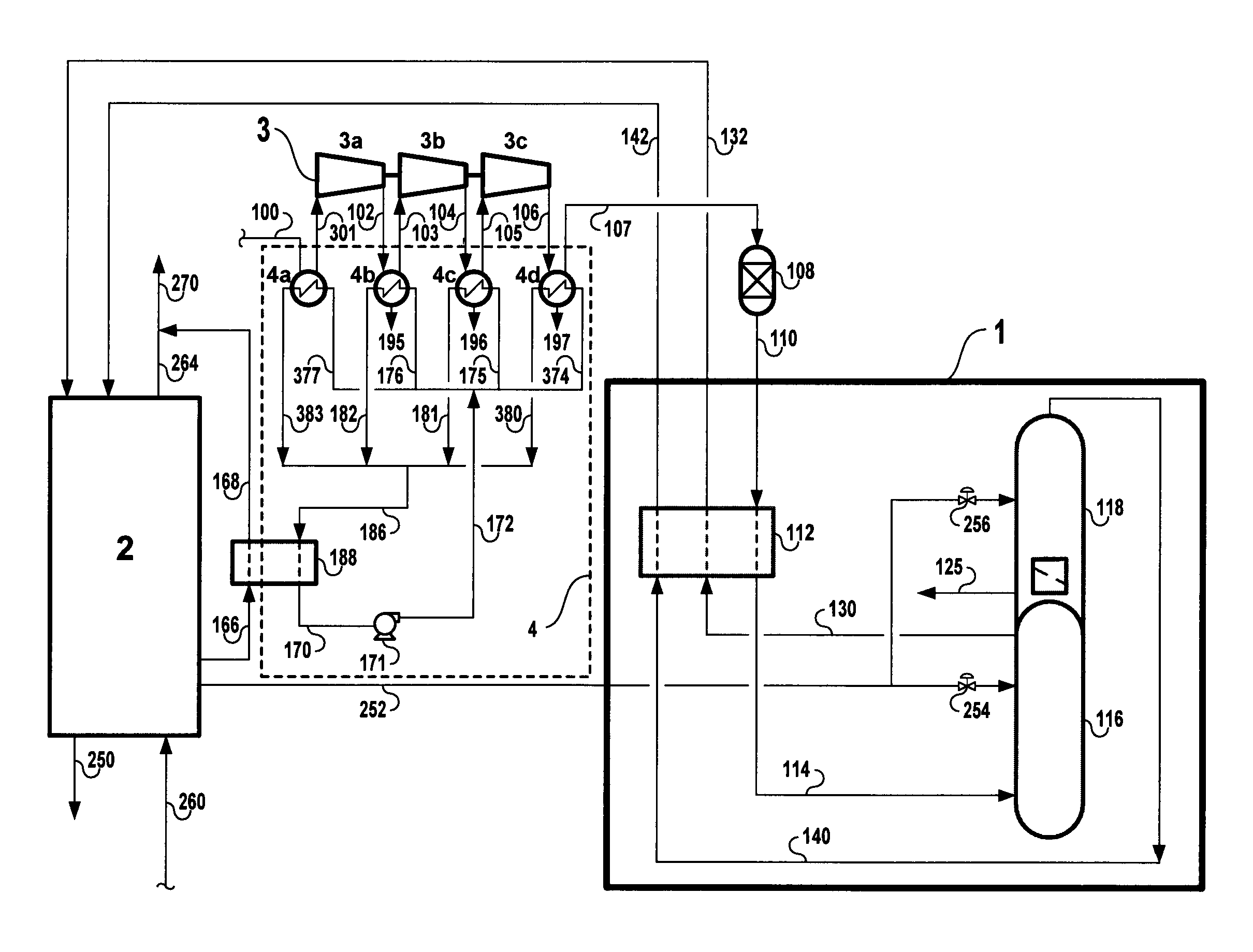
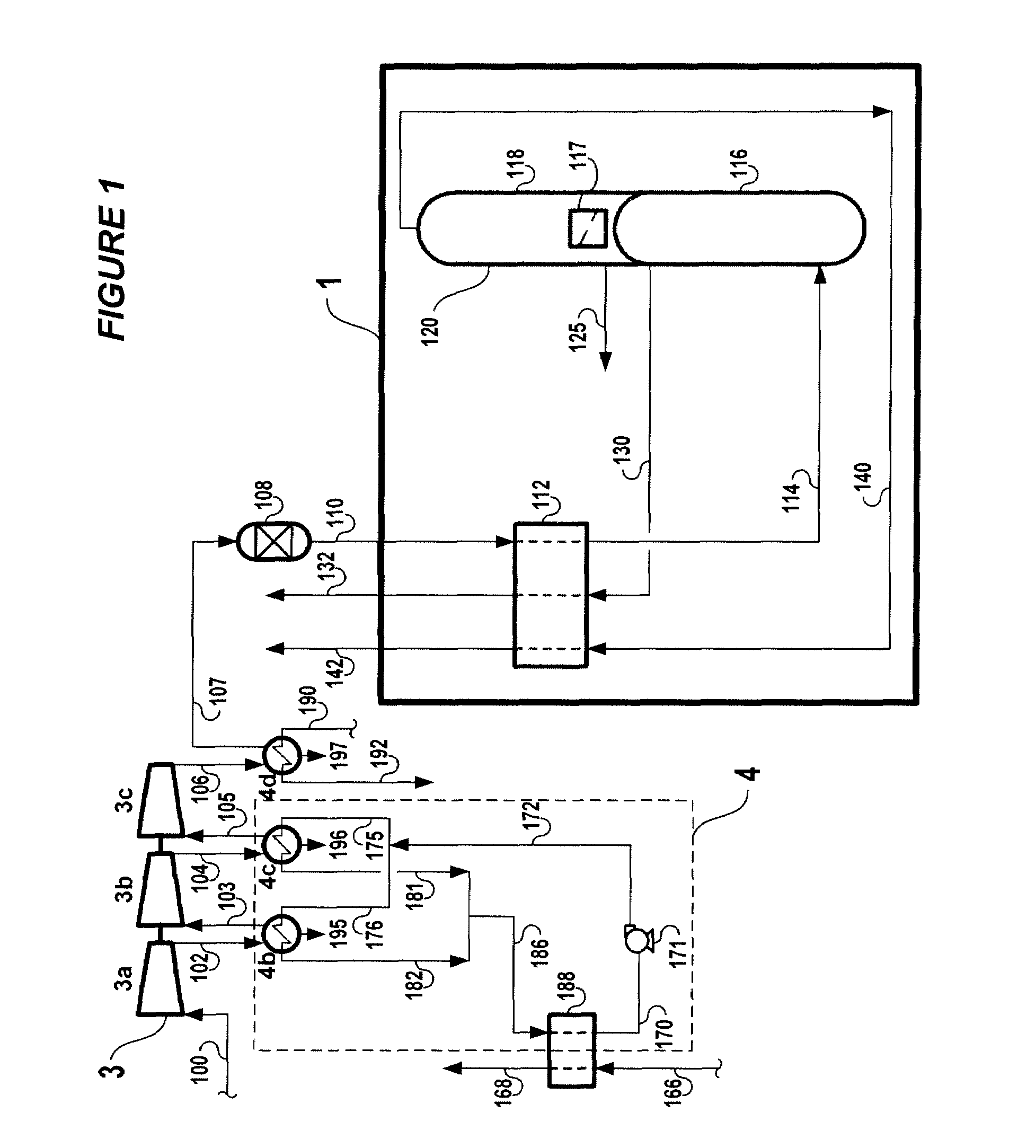
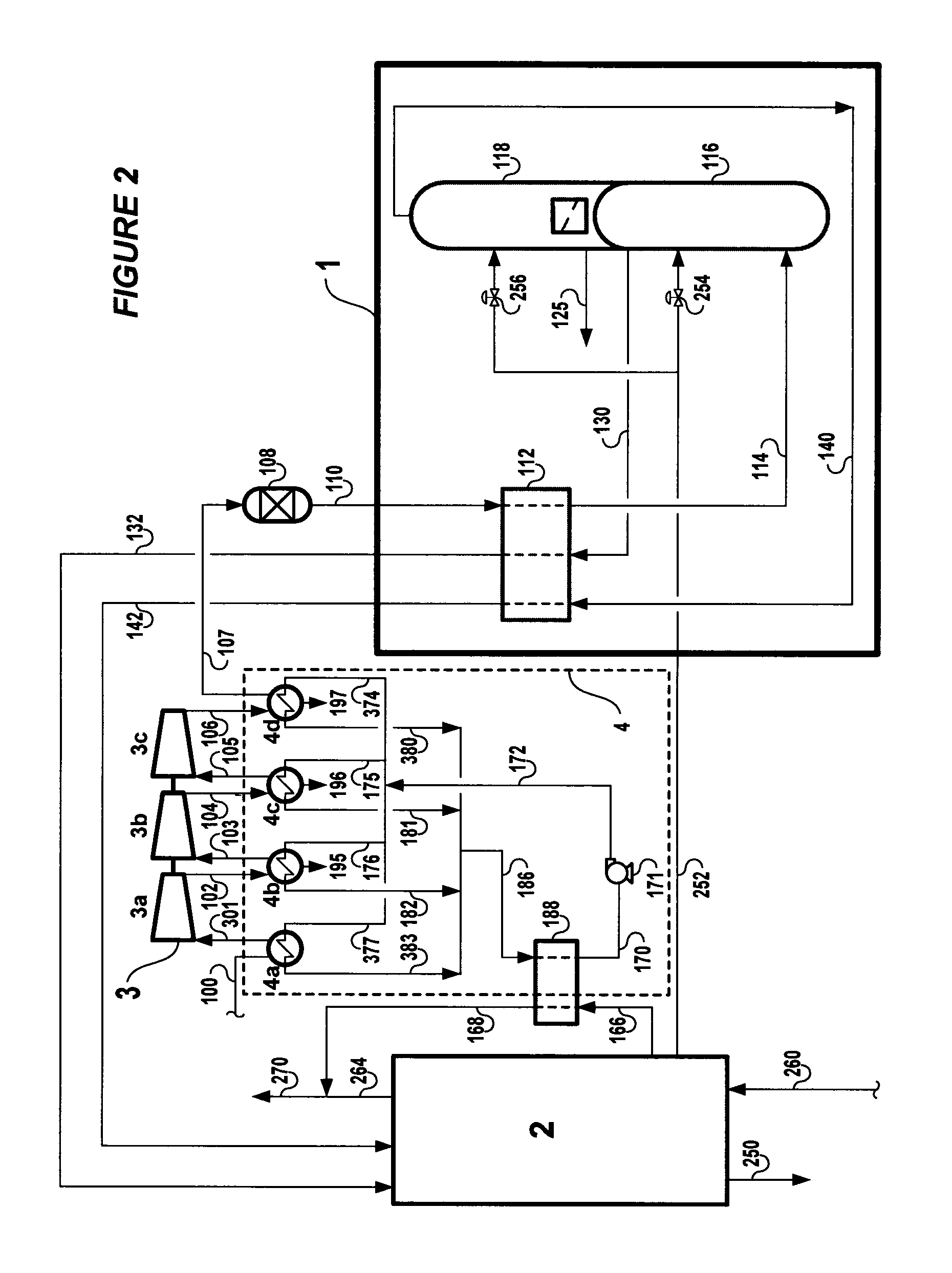
[0057]One of the processes presented in this Example uses the “low temperature” refrigeration of LNG as the source of refrigeration for cooling the ICM. In this process, stream 166 consists of a portion of the fresh LNG supply.

[0058]Another process, one that uses the relatively “high temperature” refrigeration of cold natural gas as the source of refrigeration for cooling the ICM, is also presented. In this second process, instead of stream 166 consisting of a portion of fresh LNG supply, stream 166 consists of a cold natural gas stream withdrawn from the liquefier unit 2. In effect, the liquefier unit 2 in this process is coupled to the cold compression scheme for the air stream 100.

[0059]Both of these processes (“low temperature ICM cooling” and “high temperature ICM cooling”) can be compared with a “base case” process that does not at all involve cold compression of the air stream 100.

[0060]These different processes were simulated on the basis of producing 1000 metric tons per da...


PUM


Abstract

An air stream is compressed in multiple stages using refrigeration derived from a refrigerant comprising natural gas for inter-stage cooling. The possibility of natural gas leaking into the air stream is reduced by use of an intermediate cooling medium (“ICM”) to transfer the refrigeration from the refrigerant to the inter-stage air stream. The compressed air stream can be fed to a cryogenic air separation unit that includes an LNG-based liquefier unit from which a cold natural gas stream is withdrawn for use as said refrigerant.

Description

BACKGROUND OF THE INVENTION[0001]It is known in the art that the power required to compress a gas can be reduced by compressing the gas in stages in order to allow for cooling of the gas between stages. Eventually a balance is reached where the power savings are offset by the capital cost of dividing the compression step into more and more stages, but depending on the compression duty at issue and the relative costs of power vs. capital, the optimum number of stages will often be several. This is particularly true in the case of compressing an air stream that is fed to a typically sized cryogenic air separation unit (“ASU”) wherein the air stream is separated into one or more product streams typically including at least a nitrogen product and an oxygen product, often an argon product, and less often krypton and xenon products.[0002]It is also known in the art that the power savings are proportional to the inter-stage cooling temperature. In particular, cooling to a sub-ambient tempe...

Claims


Application Information

Patent Timeline
Patent Type & Authority Patents(United States)
IPC IPC(8): F25J1/00F25J3/00
CPCF25J1/0015F25J1/0221F25J1/0234F25J3/04018F25J3/04157F25J3/04224F25J3/04266F25J3/04351F25J3/04412F25J2210/62F25J2230/02F25J2230/04F25J2270/904F25J2205/04F25J1/00
Inventor DEE, DOUGLAS PAULHERRON, DONN MICHAELCHOE, JUNG SOO
Owner AIR PROD & CHEM INC
Why Eureka
Try Eureka