Recoil impulse generator for a weapon simulator

a technology of recoil generator and weapon simulator, which is applied in the field of recoil generator for weapon simulator, can solve the problems of high energy consumption, small recoil force that can be generated, and strong electromagnet, and achieve the effects of generating realistic recoil force, frequent replacement of propellant cartridges, and sufficient spa

Inactive Publication Date: 2013-12-17
E SIGMA TECH
View PDF8 Cites 8 Cited by
  • Summary
  • Abstract
  • Description
  • Claims
  • Application Information

AI Technical Summary

Benefits of technology

[0009]It is therefore the object of the invention at issue to provide an improved recoil impulse generator for a weapon simulator that generates realistic recoil forces and at the same time avoids the disadvantages of prior art. In particular the frequent replacement of propellant cartridges is to be avoided. Likewise undesirable high electromagnetic fields, as they are generated by strong electromagnets, should be avoided. In addition the weapon simulator should not exceed the dimensions, weight, balance, and the shape of an actual weapon, in particular not a hand gun, and it should provide sufficient space for installing a target-finding or target-acquisition unit despite the installation of the recoil impulse generator. Finally the recoil impulse generator should be universally adaptable to different firearm simulators so that pistols, long guns as well as also other weapons that generate recoil can be equipped therewith.
[0012]The electric motor is preferably a brush-less synchronous motor that can achieve high rotational speed (approximately 20,000 min-1 to 80,000 min-1). In a preferred embodiment the electric motor can be coupled to the spindle via a transmission or it can also operate as a transmission-less direct drive. The transmission is implemented for example with a reduction ratio of 2:1 to 5:1 and can effect an inversion of rotation. It is of importance that a relatively high rotational speed of the spindle (or a high torque at lower rotational speed) is achieved in order to convey the slide from the unstressed position into the stressed position in a short time. This time corresponds to the duration of automatic reloading in the case of semi-automatic hand guns and should preferably require less than one second. In order to simulate such fast reloading times the electric motor is continuously operated during a shot sequence according to the invention, so that the drive forces act immediately on the slide while the coupling engages. This additionally has the advantage that the startup torque that necessarily acts on the hand gun simulator and which arises during startup and braking of the electric motor, no longer appears, or at least to a lesser degree, during the shot sequence, as a result of which targeting errors are avoided or reduced. A symmetrically constructed coupling serves the same purpose in a modified embodiment, wherein it engages the spindle from two facing sides so that the resulting moments are largely compensated.
[0013]In a particularly preferred embodiment the rotational speed of the electric motor can be reduced while the coupling is not engaging the spindle. The forces that arise while engaging under load and the associated wear can be significantly reduced thereby.

Problems solved by technology

In this constellation either strong drive elements have to be used or the recoil force that can be generated is too small.
The generation of large recoil simulation forces would require a very strong electromagnet, which structurally could barely be accommodated in a hand gun and additionally would have a high energy consumption.
The described mechanism is only used occasionally to cock the weapon since firearm malfunctions occur only occasionally, so that the motor also is not designed for permanent use.

Method used


Image

  • Recoil impulse generator for a weapon simulator
  • Recoil impulse generator for a weapon simulator
  • Recoil impulse generator for a weapon simulator

Examples


Embodiment Construction

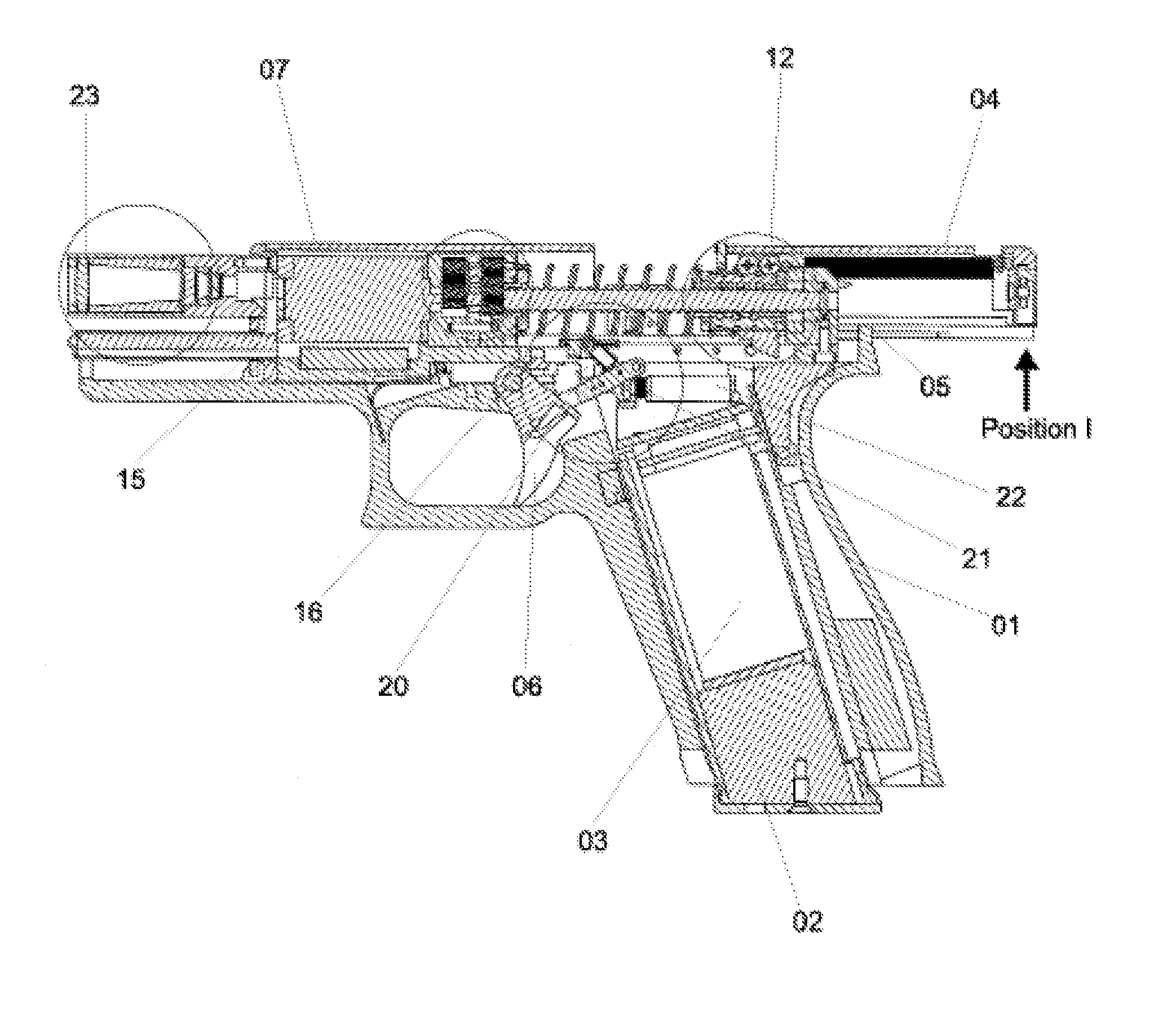
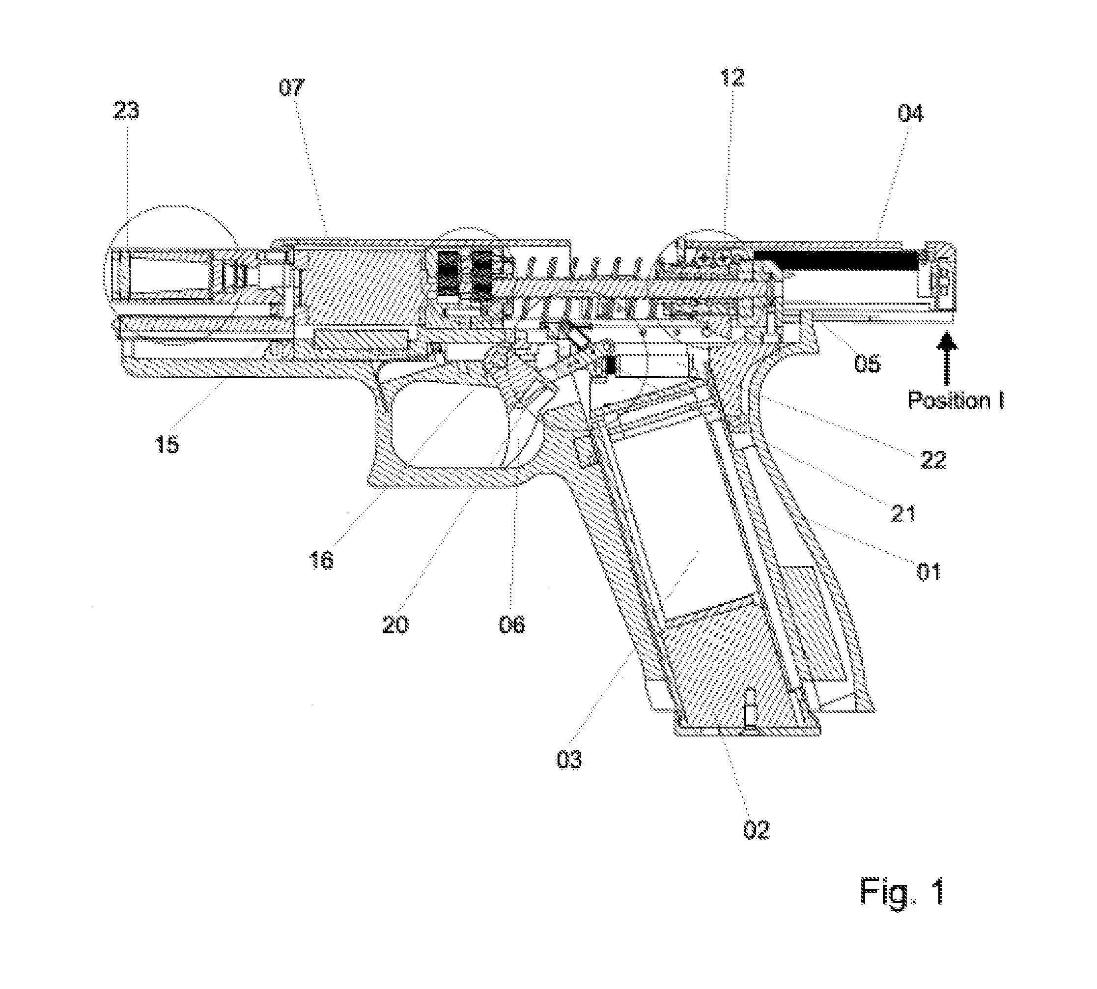
[0022]FIG. 1 displays a cut view of a hand gun simulator that is as accurate a reproduction in shape and dimensions of an actual hand gun (in this case a pistol) as possible in order to be able to design the simulation as realistically as possible. The simulator encompasses a pistol housing with a hand grip 01, wherein a magazine slot is provided. A simulator magazine 02 is inserted in the magazine slot instead of the usual cartridge magazine and it contains for example a storage battery 03 as an energy source. Furthermore a slide 04 is provided that glides along the slide-way 05 in the shooting direction and is part of the impulse mass. Furthermore the hand gun simulator encompasses a trigger 06 and a barrel 07. The recoil impulse generator is disposed in the axial direction of the barrel 07.

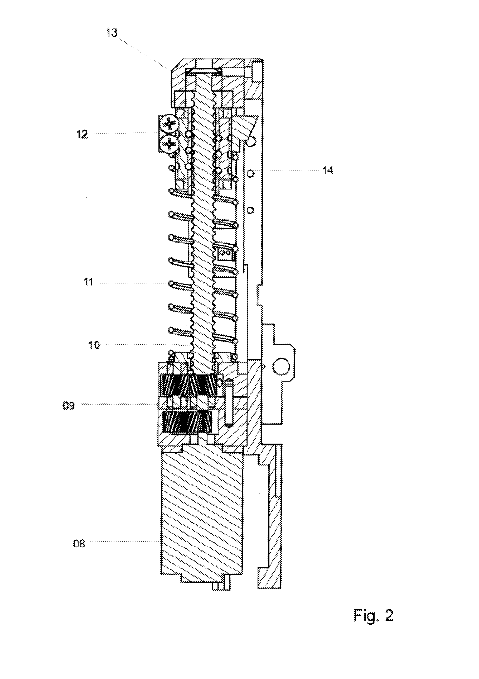
[0023]FIG. 2 displays a detail representation of the most important elements of the recoil impulse generator in a cut view. An electric motor 08 that is used as a drive and that operates for ex...


PUM


Abstract

The invention relates to a recoil impulse generator for a weapon simulator comprising a force storage element and an impulse mass that can be moved and that is moved from a stressed to an unstressed position with a triggering element is actuated in order to simulate a recoil impulse. The recoil impulse generator comprises a drive that drives a spindle uninterruptedly during a shot sequence simulating several shots; a coupling that is connected to the impulse mass and to the force storage element and that engages in the spindle in an engaged state and that is moved along the spindle by means of rotation of the spindle in order to bring the impulse mass into the stressed position again the force applied by the force storage element; a disengaging means that switches the coupling to a disengaged state when the impulse mass has reached the stressed position; and an engaging means that switches the coupling to the engaged state when the impulse mass has reached the unstressed position.

Description

CROSS-REFERENCE TO RELATED APPLICATIONS[0001]This application is a national stage application of PCT / EP2010 / 051502, filed Feb. 8, 2010, which claims priority to European application no. 09152527.9, filed Feb. 11, 2009, the entirety of which is hereby incorporated by reference.BACKGROUND OF THE INVENTION[0002]The present invention concerns a recoil impulse generator for a weapon simulator comprising a force storage element and a movable impulse mass that is moved from a stressed to an unstressed position when a trigger element is actuated by the force storage element in order to generate a recoil impulse. In general the recoil of the most varied weapons can be simulated with a recoil impulse generator. The recoil impulse generator considered here is suitable preferably for hand gun simulators.[0003]US 2008 / 0155875 A1 describes a mechanism for the recoil impulse generation in a toy gun. There an electric motor drives a piston of a compressed air cylinder via a multi-part reduction gea...

Claims


Application Information

Patent Timeline
Patent Type & Authority Patents(United States)
IPC IPC(8): F41A33/00
CPCF41A33/06
Inventor MARKERT, MARTINMUELLNER, JOSEFBONITZ, BJOERN
Owner E SIGMA TECH
Why Eureka
Try Eureka