Piezoelectric thin-film filter
a thin-film filter and piezoelectric technology, applied in the direction of impedence networks, electrical devices, etc., can solve the problems of deteriorating steepness of the shoulder characteristic of the filter, increasing insertion loss, etc., and reducing the ripple in the passband. , the effect of reducing the insertion loss
- Summary
- Abstract
- Description
- Claims
- Application Information
AI Technical Summary
Benefits of technology
Problems solved by technology
Method used
Image
Examples
first preferred embodiment
[0061]A piezoelectric thin-film filter 10 according to the first preferred embodiment will be described with reference to FIGS. 1 to 6B.
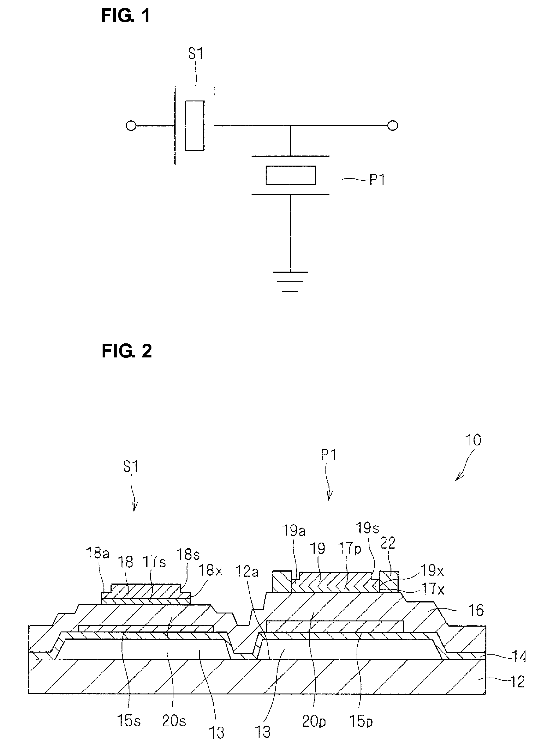
[0062]As shown in a circuit diagram of FIG. 1, the piezoelectric thin-film filter 10 according to the first preferred embodiment includes a ladder-type filter(s) including a series resonator S1 and a parallel resonator P1 and provided in one or two or more stages.
[0063]That is, in the piezoelectric thin-film filters 10, using the one stage shown in FIG. 1 as a basic unit, the ladder-type filters are provided in multiple stages and cascade-connected as necessary in accordance with the specification. An inductor may be connected to a resonator in series.
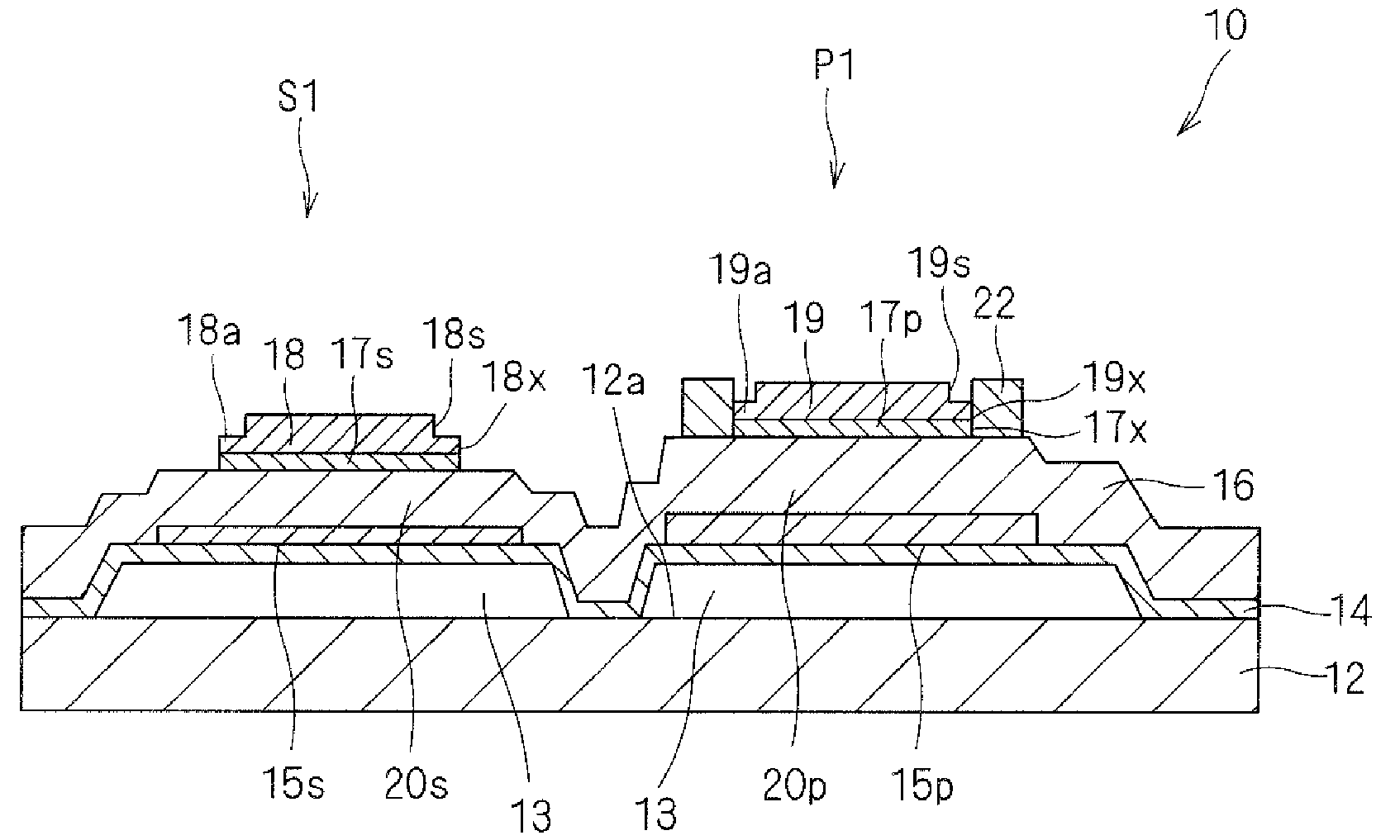
[0064]The series resonator S1 and parallel resonator P1 are configured as shown in a sectional view of FIG. 2.
[0065]A supporting layer 14, lower electrodes 15s and 15p, a piezoelectric thin film 16, upper electrodes 17s and 17p, frequency adjustment films 18 and 19, and an additional film 22 are lamina...
second preferred embodiment
[0097]As with the filter according to the first preferred embodiment, a filter according to the second preferred embodiment is a one-stage or multiple-stage, ladder-type filter formed by combining a type A resonator and a type B resonator.
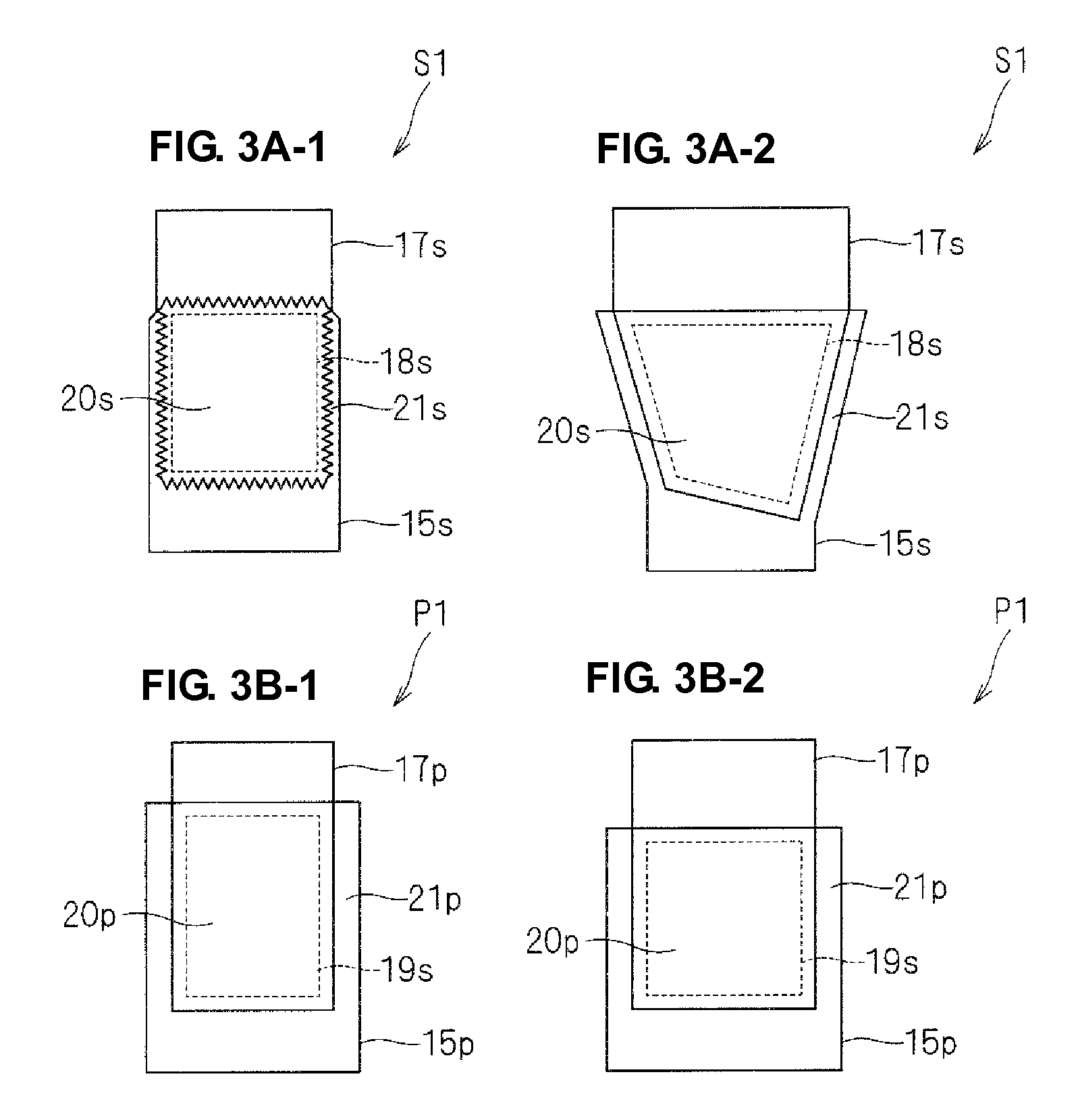
[0098]The filter according to the second preferred embodiment uses a type A resonator including a vibration portion, a plan view shape of which is an asymmetrical polygon shown in FIG. 3A-2 and a type B resonator including a vibration portion, a plan view shape of which is a square shown in FIG. 3B-2. As with the first preferred embodiment, the second preferred embodiment uses a type A resonator as the series resonator S1 having a resonator capacitance smaller than the reference value (e.g., about 1.2 pF) and a type B resonator as the parallel resonator P1 having a resonator capacitance larger than the reference value (e.g., about 1.2 pF).
[0099]As shown in Table 2 below, the filter according to the second preferred embodiment is different from the ...
third preferred embodiment
[0102]A filter according to the third preferred embodiment will be described with reference to FIGS. 7 to 8.
[0103]As shown in a circuit diagram of FIG. 7, the filter according to the third preferred embodiment preferably is a three-stage, ladder-type filter including series resonators S1 to S4 and parallel resonators P1 to P3. As with the filter according to the first preferred embodiment, the three-stage, ladder-type filter is formed by combining type A resonators and type B resonators. That is, the filter according to the third preferred embodiment uses type A resonators including a vibration portion, a plan view shape of which an asymmetrical polygon shown in FIG. 3A-2 and type B resonators including a vibration portion, a plan view shape of which is a square shown in FIG. 3B-2.
[0104]The resonators S1 to S4 and resonators P1 to P3 are disposed as shown in a layout diagram of FIG. 8. In particular, by combining the resonators S1 to S4 and P1 to P3 each including a vibration portio...
PUM
 Abstract
Description
Claims
Application Information
 - R&D
- Intellectual Property
- Life Sciences
- Materials
- Tech Scout
- Unparalleled Data Quality
- Higher Quality Content
- 60% Fewer Hallucinations
Browse by: Latest US Patents, China's latest patents, Technical Efficacy Thesaurus, Application Domain, Technology Topic, Popular Technical Reports.
© 2025 PatSnap. All rights reserved.Legal|Privacy policy|Modern Slavery Act Transparency Statement|Sitemap|About US| Contact US: help@patsnap.com


