Molding method and mold therefor

a synthetic resin and mold technology, applied in the field of synthetic resin product molds and methods, can solve the problems of minute air bubbles trapped in the liquid mixture, surface imperfections of the final molded product, and unsatisfactory possibility

Active Publication Date: 2013-12-31
KAGA SANGYO
View PDF19 Cites 4 Cited by
  • Summary
  • Abstract
  • Description
  • Claims
  • Application Information

AI Technical Summary

Benefits of technology

[0009]The agitating / degassing technique disclosed in JP H11-104404 may allow the liquid mixture to be effectively degassed before the liquid mixture is injected into a mold for molding, without any bubbles being entrained in the liquid mixture.

Problems solved by technology

However, when a molding method is performed using a mixture of high-viscosity liquid materials, an undesirable possibility exists that minute air bubbles will be trapped in the liquid mixture during the process of mixing and agitating the liquid materials, especially in case the liquid materials are mixed and agitated without any special care.
Further, an additional possibility exists that high-viscosity liquid materials will trap ambient air while being injected into a mold, and the trapped air will end up as air bubbles entrained in the molded material.
Still further, when the molding is performed using high-viscosity liquid materials, the inner surface of a mold (that may have, e.g., very small gaps, undercuts, or the like) may not be completely filled and covered with the liquid mixture (i.e., the liquid mixture does not reach all portions of the entire inner surface of the mold), which may undesirably lead to surface imperfections on the final molded product.
However, when at least one of liquid components has a high viscosity, air bubbles can become undesirably entrained in the liquid mixture if the liquid mixture is degassed without any special care.
In any event, if air bubbles are contained in the liquid mixture in the mold or if the inner surface of the mold is not completely filled with the liquid mixture, then the final molded product will have defects.
However, an undesirable possibility still exists that, when the liquid mixture is being injected into the mold for molding after it has been agitated / degassed, the liquid mixture will trap ambient air, and the trapped air will form air bubbles in the liquid mixture held in the mold.
In addition or in the alternative, the molding process could undesirably proceed with the inner surface of the mold not completely filled and coated with the liquid mixture.
For these reasons, the above-described known technique does not adequately eliminate or minimize the risk that the final molded product will contain air bubbles within the interior of the product or on the surface thereof
Incidentally, because the female mold forms the exterior surface of a molded product, it is possible that the exterior surface of a final molded product will have defects if the female mold is not adequately filled, coated or covered with the liquid mixture prior to the curing / hardening of the liquid mixture.

Method used


Image

  • Molding method and mold therefor
  • Molding method and mold therefor
  • Molding method and mold therefor

Examples


first embodiment

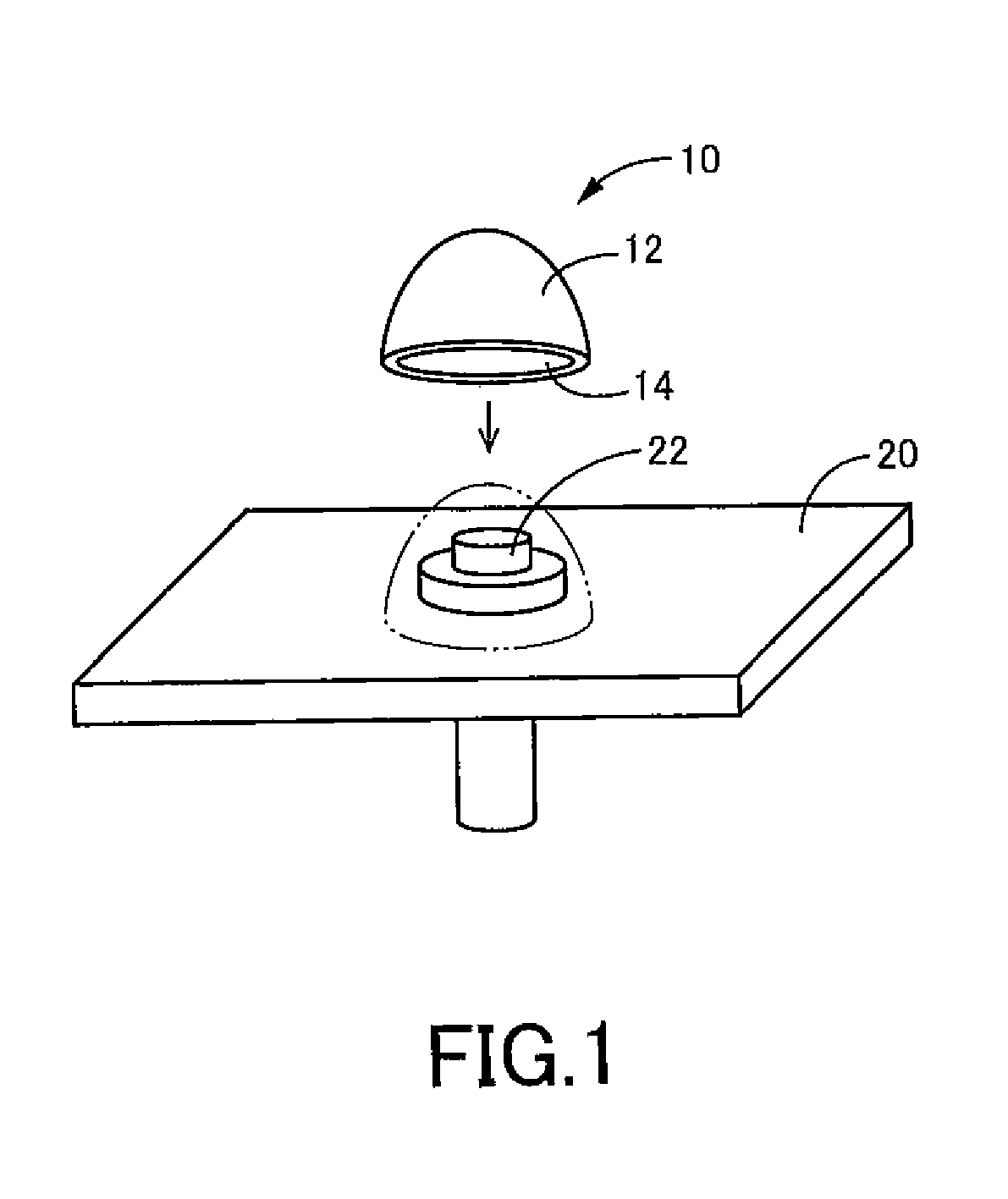
[0115]FIG. 1 illustrates in a perspective view a cap 10 as a molded product to be molded using the cap molding method according to the present teachings.

[0116]The cap 10 is made of synthetic resin and includes a shell 12 that forms a generally hemispherical, hollow shape. The shell 12 includes an outer surface and an inner surface, which both form a generally hemispherical shape, thereby defining a recess (hollow portion) 14, which forms a generally hemispherical shape, within the shell 12.

[0117]The cap 10 will be attached to a fastener, with which a fastened member is fastened, for the purpose of enclosing or covering an outside surface of at least a portion of the fastener, to thereby protect at least a portion of the fastener that would otherwise be exposed.

[0118]In the example illustrated in FIG. 1, the fastened member is a panel member 20 made of synthetic resin, and the fastener is a bolt (alternatively, a screw, a nut or a rivet) 22, with which the panel member 20 is fastened...

third embodiment

[0269]In the third embodiment, as described above, the mold unit 140 is configured to include the guide pins 160 (each is an example of the “first member” set forth in the above mode (5)), which integrally move with the male mold 144, and the elongated guide holes 162 (each is an example of the “second member” set forth in the same mode), which integrally move with the female mold 142. The guide pins 160 move along the elongated guide holes 162, each having a predetermined path, due to the cooperative action of the inertial force, which that acts on the male mold 144 in the rotational direction of the male mold 144 because of its rotation and which varies over time at least in the direction of the force, and the axial centrifugal force, which acts on the male mold 144 because of its orbiting and which varies over time in the magnitude of the force. As a result, the operational state of the male mold 144 is switched between a state, in which the male mold 144 is prevented from closel...


PUM

PropertyMeasurementUnit
temperatureaaaaaaaaaa

Abstract

Molding methods and molds for making a synthetic resin molded product include disposing a curable liquid resin mixture in a recess of a female mold. The curable liquid resin mixture is then simultaneously agitated and degassed by a mixer while under a partial vacuum. More specifically, at least the female mold is orbited around an orbital axis while being rotated about a rotational axis that is eccentric to the orbital axis. After being thoroughly mixed and degassed, the liquid mixture is then cured in the mold unit.

Description

CROSS-REFERENCE[0001]This application claims priority to U.S. provisional patent application No. 61 / 325,976 filed on Apr. 20, 2010, the entire contents of which are incorporated herein by reference.TECHNICAL FIELD[0002]The invention relates to methods and molds for molding a synthetic resin product from a liquid mixture using a mold unit having a female mold and a male mold, which define a molding cavity therebetween when closely engaged with each other.BACKGROUND ART[0003]There is a long-felt need in the art for molding methods and molds capable of manufacturing high-precision products (e.g., mechanical parts, electric parts, electronic parts, or the like). The liquid mixture used for molding can be a mixture of different liquid materials, i.e., a liquid mixture, and these liquid mixtures may include high-viscosity liquid materials.[0004]However, when a molding method is performed using a mixture of high-viscosity liquid materials, an undesirable possibility exists that minute air ...

Claims


Application Information

Patent Timeline
Patent Type & Authority Patents(United States)
IPC IPC(8): B29C43/22A01J21/00
CPCB29C45/14065B29C37/006B29C67/246B29C45/14639B29L2011/00B29C45/63B29C35/16B29K2101/10
Inventor MIZOGUCHI, OSAMUNOMURA, TAKAYUKITSUJIKAWA, HITOSHIIKEDA, YOSHIKI
Owner KAGA SANGYO
Why Eureka
Try Eureka