

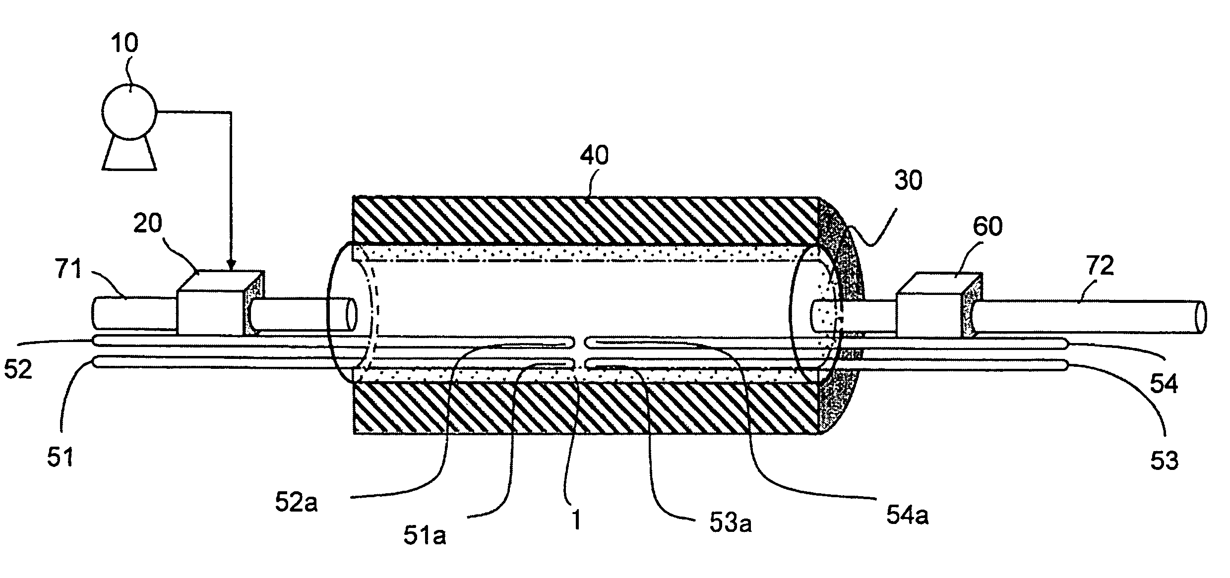
Fluid reforming apparatus for maintaining thermal conductivity of a fluid in a flow channel
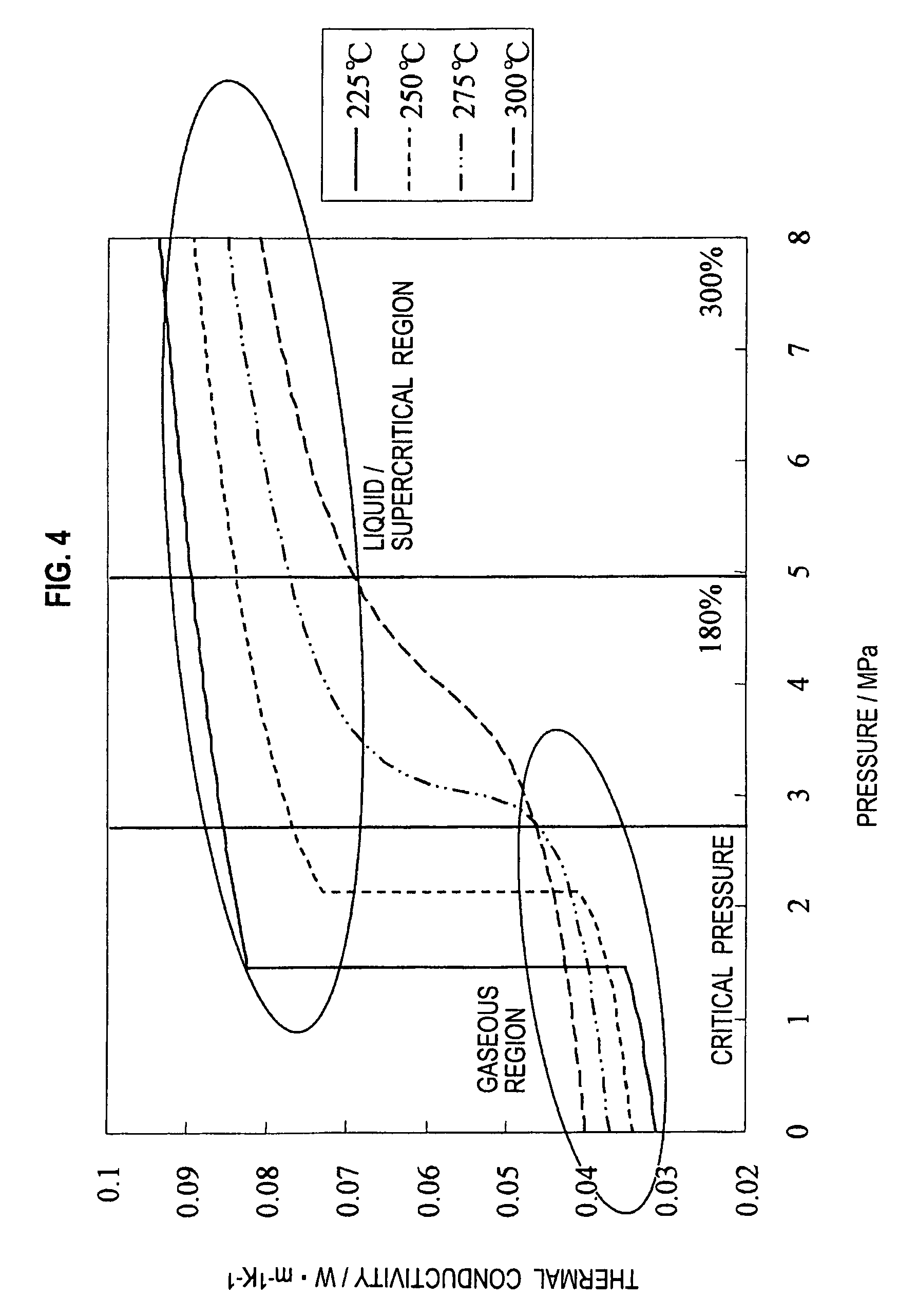
a technology of thermal conductivity and fluid, which is applied in the direction of combustion air/fuel air treatment, process and machine control, instruments, etc., can solve problems such as carbon deposition, and achieve the effect of significantly reducing the thermal conductivity of the fuel in the region 1 and reducing the fuel density
- Summary
- Abstract
- Description
- Claims
- Application Information
AI Technical Summary
Benefits of technology
Problems solved by technology
Method used
Image

Examples
example 1
[0072]The fluid reforming apparatus as shown in FIG. 7 was used. Note that the heating chamber has a cylindrical shape with a cross-sectional area of 1 cm2 and a length of 10 cm, and the same is applied also to the following examples. Then, the state of heptane in the heating chamber was changed by the fluid heating device and the pressure control device. Pressures and densities of heptane at respective temperatures in this case were measured. Obtained results are shown in FIG. 9. FIG. 9 is a graph showing relationships between the pressures and densities of heptane at the respective temperatures.
example 2
[0073]The fluid reforming apparatus as shown in FIG. 7 was used, and the state of the gasoline in the heating chamber was changed by the fluid heating device and the pressure control device. Pressures and densities of the gasoline at respective temperatures in this case were measured. Obtained results are shown in FIG. 10. FIG. 10 is a graph showing relationships between the pressures and densities of the gasoline at the respective temperatures.
example 3
[0074]The fluid reforming apparatus as shown in FIG. 7 was used, and the state of the light oil (JIS No. 2) in the heating chamber was changed by the fluid heating device and the pressure control device. Pressures and densities of the light oil at respective temperatures in this case were measured. Obtained results are shown in FIG. 11. FIG. 11 is a graph showing relationships between the pressures and densities of the light oil at the respective temperatures.
[0075]The entire contents of Japanese Patent Application No. 2006-213213 (filed on Aug. 4, 2006) and Japanese Patent Application No. 2007-198633 (filed on Jul. 31, 2007) are incorporated herein by reference.
[0076]The description has been made above of the contents of the present invention along the embodiment and the examples; however, the present invention is not limited to the description of these, and it is obvious for those skilled in the art that a variety of modifications and improvements are possible.
PUM
 Abstract
Description
Claims
Application Information