Thermodynamic cycles with thermal diluent

a technology of thermal dilution and thermodynamic cycles, which is applied in the direction of lighting and heating apparatus, machine/engine, heating types, etc., can solve the problems of low net specific power, poor relative control of peak fluid temperature, and little spatial control of transverse fluid temperature profiles (or distributions)

Active Publication Date: 2014-01-21
VAST HLDG LLC
View PDF88 Cites 31 Cited by
  • Summary
  • Abstract
  • Description
  • Claims
  • Application Information

AI Technical Summary

Benefits of technology

[0023]According to another aspect of the invention, VAST combustors are preferably provided and configured operable to control VAST Cycles under near stoichiometric conditions while keeping pollutants low, such as described in the above-mentioned Ginter, patents, and Hagen et al., patent applications. They are preferably configured to accommodate all the liquid and / or vapor diluent desired upstream of the expander by replacing at least some excess diluent air. More preferably, the diluent delivery is operable to displace some to all excess air from the Brayton cycle to near stoichiometric conditions, e.g., by adding diluent (e.g., water and / or steam) sufficient to exceed one or more of the air saturation limit, a steam generation limit, a premixed combustibility and / or flame stability limit, and a small droplet combustion quench limit. Compressors are preferably resized relative to turbines to accommodate the lower oxidant containing fluid flows, providing major cost savings.
[0030]In still another aspect of the invention, an object is to control major pollutant levels below desired limits while operating with less excess oxidant than a Brayton cycle, preferably near stoichiometric conditions. VAST combustors capable of controlling transverse distribution of fluid delivery are preferably utilized, being operable to provide transverse distributions of lower relative oxidant (or relative air) than Brayton cycles, preferably near stoichiometric conditions and at a prescribed fluid temperature, while achieving low pollutant emissions. (The relative oxidant / fuel ratio is the actual oxidant / fuel ratio divided by the stoichiometric oxidant / fuel ratio.) In such an embodiment, by using a combustor operable to constrain peak combustion temperatures while using low excess oxidant, the emissions of a combustion byproduct (such as oxides of nitrogen NOx) are preferably reduced and more preferably controlled below an upper NOx concentration limit. More preferably the rate of byproduct emissions is maintained below a prescribed emissions rate (mass per time, or mass per energy kg / MWh). By using a combustor operable to control transverse temperature distributions and fluid composition distributions, good fuel oxidation may be readily achieved sufficient to maintain a concentration of partially oxidized fuel component less than a prescribed concentration of partially oxidized fuel. More preferably, emission rate of one of carbon monoxide, and / or a partially oxidized or residual fuel component below a prescribed emissions rate (mass per time or mass per energy kg / MWh)

Problems solved by technology

The prior art includes combustors and combustion systems that use diluents to cool combustion, but which provide with relatively poor control over the peak fluid temperature and little spatial control over the transverse fluid temperature profile (or distribution).
Pressurizing or compressing this excess air commonly consumes 40% to 85% (from large turbines to microturbines) of the gross turbine power recovered resulting in low net specific power.
It is difficult, however, to control the temperature profile using excess air or steam as customarily employed to cool cycle components and special mixing devices.
The problem of temperature irregularities is heightened by changes in work load or variations in ambient conditions.
This results in high capital costs from two turbines.
However, deregulation is requiring increasing cyclic power generation.
By only delivering steam, the STIG cycle is limited in its ability to recover lower temperature heat.
High water treatment costs and water availability are often stated as a major objections to more widespread use of the STIG.
This is typically limited by an air saturation limit.
While utilizing lower quality water, the HAT and EvGT cycles are limited in the amount of deliverable diluent by one or more air saturation limits.
Otherwise these RWI, HAT, and EvGT cycles have been little used, possibly because of relatively high capital costs.
It has lower costs but lower efficiency than the HAT cycle.
Conventional heat recovery methods have particular difficulty in recovering useful heat below the temperature of steam recovered by heat exchange with the expanded fluid with sufficient pressure to reinject upstream of an expander, or within a steam expander.
Much heat energy continues to be lost as the expanded fluid is exhausted.
E.g., air to air recuperators approaching 700° C. These result in high cost and expensive maintenance, where the recuperator alone may exceed 30% of system costs and 80% of the maintenance in micro-turbines.
Using diluents other than air have resulted in further expenses in diluent supply and recovery in relevant cycles for power generation such as “wet” or humid cycles like STIG and HAT.
Such processes have been expensive.
Such conventional methods add substantial expenses.
Control of pollutants to stringent legislated methods has often required additional components at substantial further capital and maintenance costs.
Many of these pollutant control devices have short lives compared to the overall plant life resulting in further maintenance expenses.
The cost of providing and treating water is frequently claimed to be a substantial hindrance.
These “combined heat and power” (CHP) applications have been limited by the design of the CHP device.

Method used


Image

  • Thermodynamic cycles with thermal diluent
  • Thermodynamic cycles with thermal diluent
  • Thermodynamic cycles with thermal diluent

Examples


Embodiment Construction

Ginter VAST Cycle

[0091]U.S. Pat. Nos. 3,651,641, 5,617,719, 5,743,080 and 6,289,666 to Ginter teach VAST thermodynamic power cycles that primarily pump liquid thermal diluent (such as water) into a thermodynamic cycle to cool the combustion, reducing the use of excess dilution air. This VAST (“Value Added Steam Technology”) cycle is a hybrid between the Brayton and Rankine cycles. It preferably uses fluid water as diluent. It preferably uses an energetic fluid formed in a VAST direct contact fluid combustor, containing both hot products of combustion and superheated steam. This hot energetic fluid is preferably expanded through an expander to generate shaft and / or electrical power. E.g., via a turbine or reciprocating engine. It may also provide Combined Heat and Power (CHP).

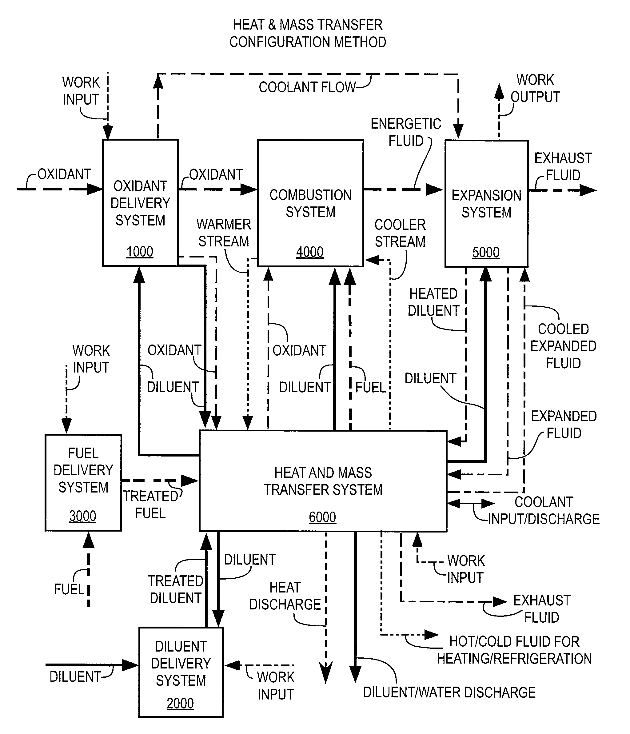
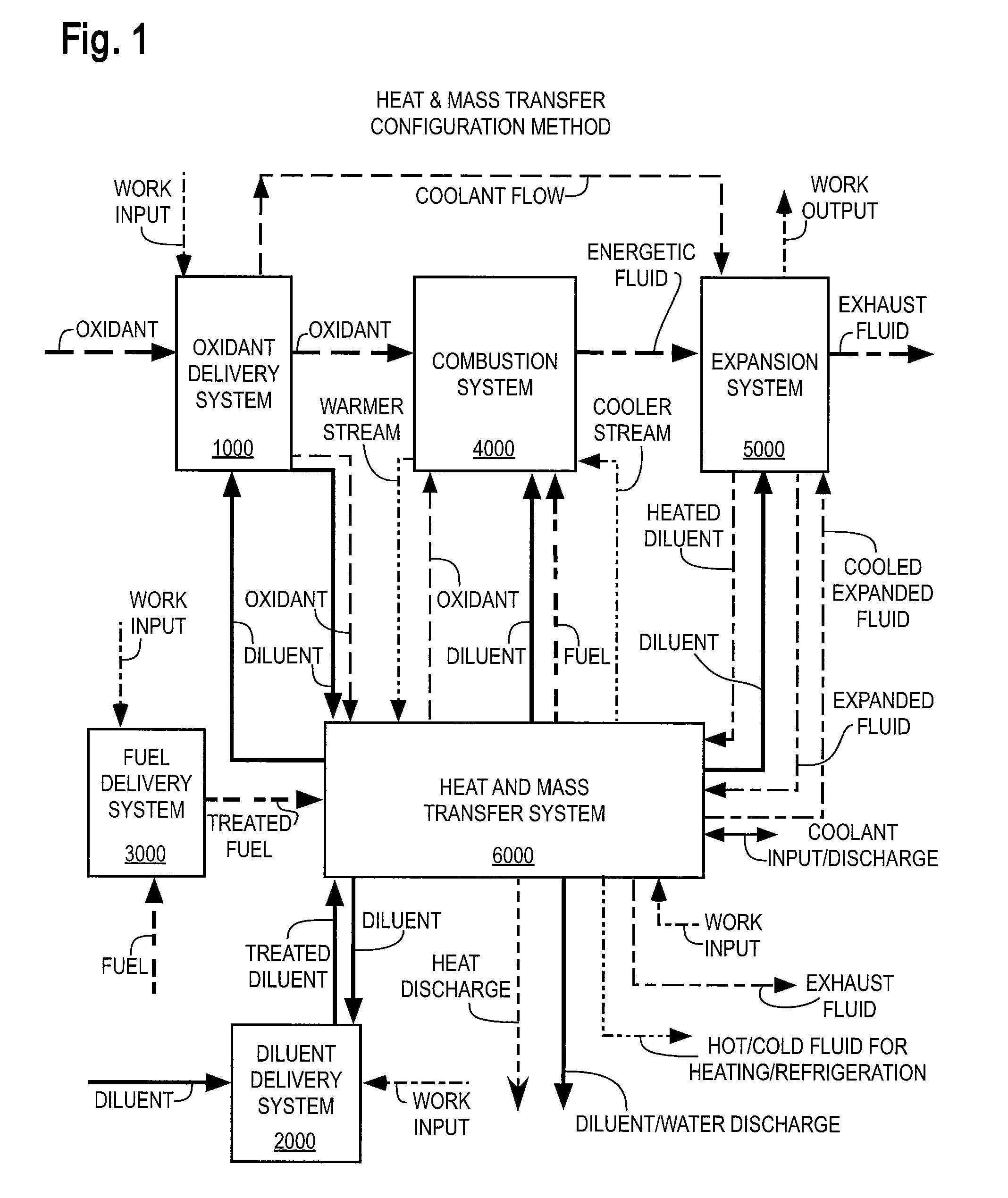
[0092]With reference to FIG. 1, the VAST thermodynamic cycles utilize a Combustion System comprising a combustor 4000 to form and deliver an Energetic Fluid to an Expansion System 5000 comprising an expansion de...


PUM


Abstract

Thermodynamic cycles with diluent that produce mechanical power, electrical power, and / or fluid streams for heating and / or cooling are described. Systems contain a combustion system producing an energetic fluid by combusting fuel with oxidant. Thermal diluent is preferably used in the cycle to improve performance, including one or more of power, efficiency, economics, emissions, dynamic and off-peak load performance, temperature regulation, and / or cooling heated components. Cycles include a heat recovery system and preferably recover and recycle thermal diluent from expanded energetic fluid to improve cycle thermodynamic efficiency and reduce energy conversion costs. Cycles preferably include controls for temperatures, pressures, and flow rates within a combined heat and power (CHP) system, and controls for power, thermal output, efficiency, and / or emissions.

Description

CROSS REFERENCE TO RELATED APPLICATIONS[0001]This application is a continuation-in-part of U.S. patent application Ser. No. 10 / 763,057 filed Jan. 22, 2004, (the “Thermodynamic Cycles application”), which, in turn, is based on and claims the benefit under 35 U.S.C. 119(e) of U.S. Provisional Application 60 / 442,096, filed Jan. 22, 2003, and 60 / 442,844 filed Jan. 24, 2003.[0002]This application is also related to Hagen et al. U.S. patent application Ser. No. 10 / 763,047 filed Jan. 22, 2004, entitled TRIFLUID REACTOR, Hagen et al. U.S. patent application Ser. No. 10 / 686,191 filed Oct. 15, 2003, entitled METHOD AND APPARATUS FOR MIXING FLUIDS, the entire disclosures of which applications are hereby incorporated herein by reference.[0003]This application is also related to Ginter U.S. Pat. Nos. 3,651,641, 5,627,719, and 6,289,666, the entire disclosures of which are hereby incorporated herein by reference.BACKGROUND OF THE INVENTION[0004]1. Field of the Invention[0005]The invention relates...

Claims


Application Information

Patent Timeline
Patent Type & Authority Patents(United States)
IPC IPC(8): F02C3/20B60H1/02F02C6/10F02C3/30F24D1/04
CPCB60H1/032Y02E20/16Y02E20/14F01K23/12F01K23/101Y02P80/15
Inventor HAGEN, DAVID L.GINTER, GARYTRAVERSO, ALBERTOGOHEEN, BILLMCGUIRE, ALLANRANKIN, JANETMASSARDO, ARISTIDEKLAUS, RONALD L.
Owner VAST HLDG LLC
Why Eureka
Try Eureka