Compact floating row cleaner

a row cleaner and compact technology, applied in the field of agricultural equipment, can solve the problems of reducing the physical space available for mounting a row cleaner, affecting the cleaning effect, and affecting the yield of the planter, so as to reduce the cost of chemical cleaning, reduce the erosion, and increase the yield

Active Publication Date: 2014-01-21
MARTIN RONALD S
View PDF14 Cites 4 Cited by
  • Summary
  • Abstract
  • Description
  • Claims
  • Application Information

AI Technical Summary

Benefits of technology

[0007]Applicant discloses and claims herein a row cleaner frame and structure, without limitations, which has particular application as an improved no-till or minimum tillage planting apparatus and or planting row unit. The present invention provides a mounting mechanism for planter row unit row cleaners. It includes an assembly for mounting the residue wheels in front of the row unit so that the row cleaner wheels are mounted in front of and to each side of a coulter, as in FIGS. 7-11. The row cleaner assembly itself is pivotally connected to the planter frame and one side of the support arm upon which the row unit coulter is mounted. The mounting of the row cleaner allows it to rise and fall about a horizontal axis, within a predetermined range, in response to either terrain elevation changes or contact with non-moveable obstructions such as rocks, large soil clods and root crowns.
[0008]A large of number of corn acres are planted with a row spacing of 30-38 inches. For various reasons, including increased yields, decreasing erosion and decreasing chemical costs, farmers are interested in reducing row spacing to less than 30 inches. Reductions to a row spacing of 15-20 inches is therefore desirable. The reduction in width between planted rows in combination with the use of row cleaners can lead to plugging of the planter row units i.e. the volume of trash flow is too high for the amount of actual physical space available between planter row units contiguously mounted on a tool bar. Furthermore, the reduced spacing between row units reduces the physical space available for mounting a row cleaner to a row unit. This problem is especially an issue for planters having a split row type, such as the 1700 Series John Deere front-fold planter. Applicant's design is of benefit and desirable. Additionally, many users wish to mount an accessory tool with the row cleaner, i.e. a coulter mounted in combination with a row cleaner for each row unit.

Problems solved by technology

The reduction in width between planted rows in combination with the use of row cleaners can lead to plugging of the planter row units i.e. the volume of trash flow is too high for the amount of actual physical space available between planter row units contiguously mounted on a tool bar.
Furthermore, the reduced spacing between row units reduces the physical space available for mounting a row cleaner to a row unit.
This problem is especially an issue for planters having a split row type, such as the 1700 Series John Deere front-fold planter.

Method used


Image

  • Compact floating row cleaner
  • Compact floating row cleaner
  • Compact floating row cleaner

Examples


Embodiment Construction

—BRIEF DESCRIPTION OF DRAWINGS

[0009]In order that the advantages of the compact floating row cleaner will be readily understood, a more particular description of the compact floating row cleaner briefly described above will be rendered by reference to specific embodiments illustrated in the appended drawings. Understanding that these drawings depict only typical embodiments of the compact floating row cleaner and are not therefore to be considered limited of its scope, the compact floating row cleaner will be described and explained with additional specificity and detail through the use of the accompanying drawings.

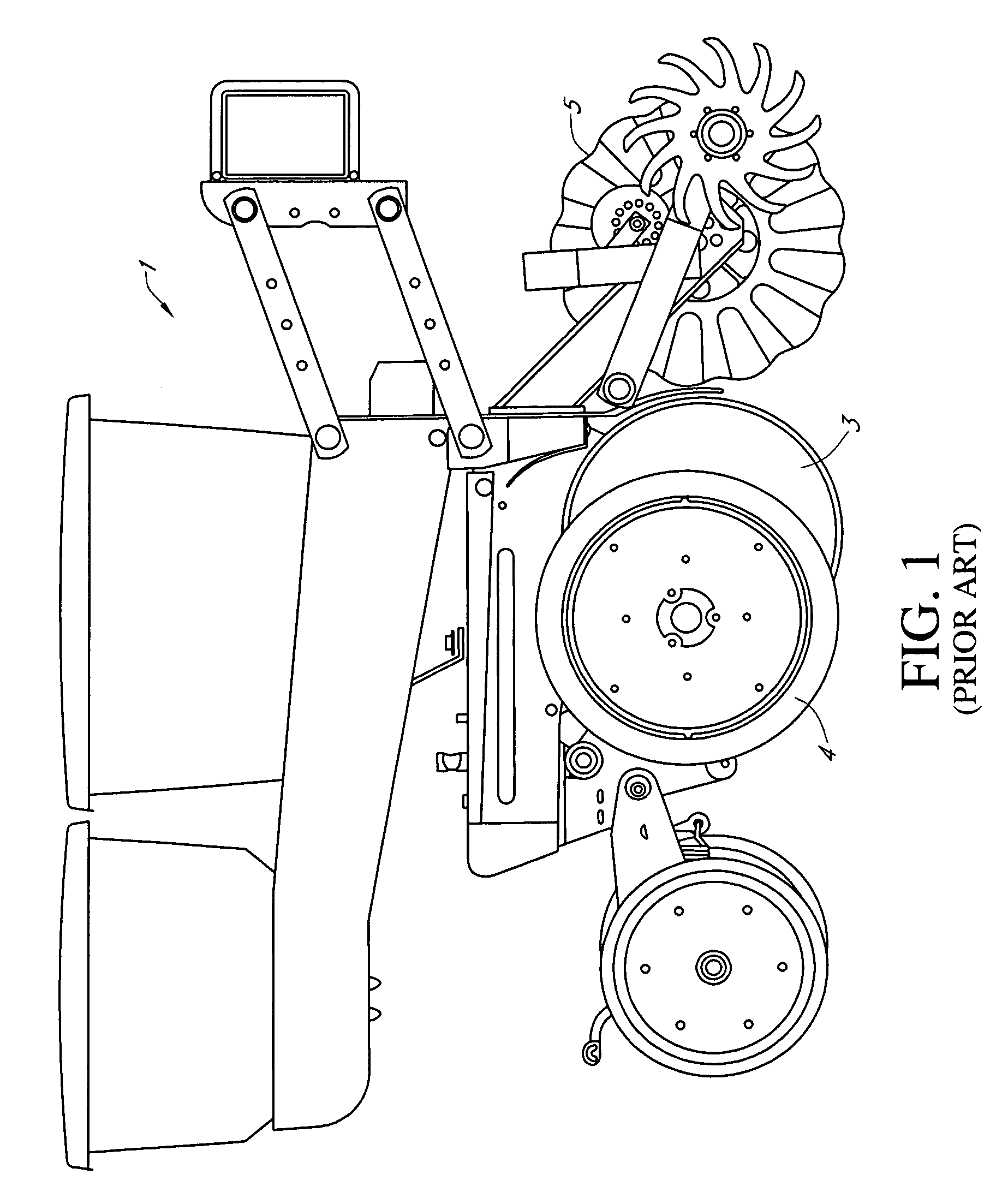
[0010]FIG. 1 illustrates a planter row unit mountable upon a tool bar as found in the prior art.

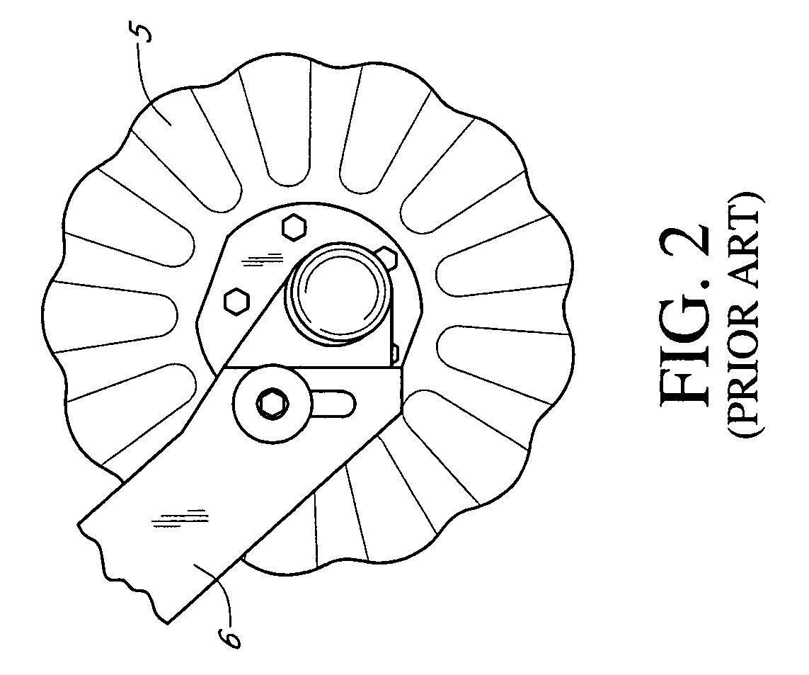
[0011]FIG. 2 provides a side view of a coulter and tool arm as found in the prior art.

[0012]FIG. 3 provides a frontal perspective view of a tool arm mounted to a front plate as found in the prior art.

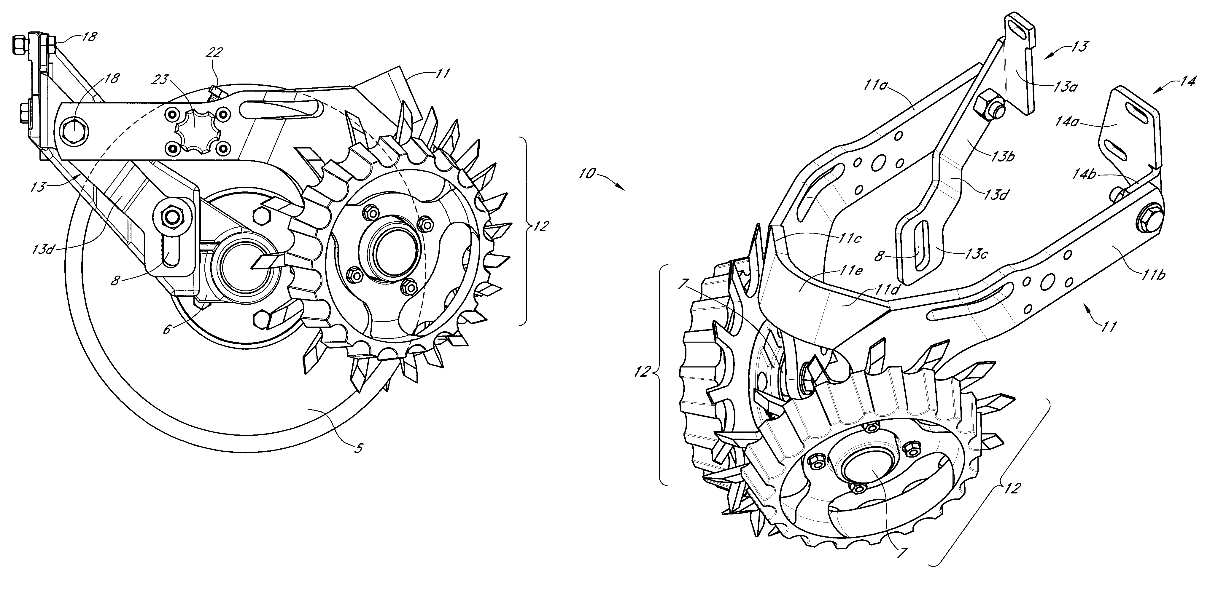
[0013]FIG. 4 provides a frontal perspective view of a tool arm with an exempla...


PUM


Abstract

A floating row cleaner assembly comprising a tool arm row cleaner mount, a row cleaner frame mounting plate, a row cleaner frame pivotally attached to the tool arm row cleaner mount and the row cleaner frame mounting plate. The periphery of the u-shaped row cleaner frame is composed of a combination of angled and curved portions to reduce the length and width of the frame to allow row cleaners to be used in combination with a coulter, or other tillage tool, and planter row unit spacing below 30 inches, while allowing necessary clearance between the row cleaner(s) and the coulter for terrain responsive operation.

Description

CROSS REFERENCE TO RELATED APPLICATIONS[0001]This application claims the filing benefit under 35 U.S.C. §119(e) of provisional U.S. Patent Application Ser. No. 61 / 124,962 filed on Apr. 21, 2008, which is incorporated by reference herein in its entirety.FIELD OF THE INVENTION[0002]The methods described herein are generally applicable to the field of agricultural equipment. The embodiments shown and described herein are more particularly for improved row cleaning for delivery of seed or fertilizer. Although in no way limiting, the present disclosure is particularly suited for minimum or no-till conditions.STATEMENT REGARDING FEDERALLY SPONSORED RESEARCH OR DEVELOPMENT[0003]No federal funds were used to develop or create the invention disclosed and described in the patent application.REFERENCE TO SEQUENCE LISTING, A TABLE, OR A COMPUTER PROGRAM LISTING COMPACT DISK APPENDIX[0004]Not Applicable.AUTHORIZATION PURSUANT TO 37 C.F.R. §1.171 (d)(c)[0005]A portion of the disclosure of this pa...

Claims


Application Information

Patent Timeline
Patent Type & Authority Patents(United States)
IPC IPC(8): A01B21/02
CPCA01B21/02A01C5/062A01B23/046A01B21/086A01C7/006Y02P60/20A01B63/24A01C5/064
Inventor MARTIN, RONALD, S.
Owner MARTIN RONALD S
Why Eureka
Try Eureka