
Circuit board manufacturing method and circuit board

A production method and circuit board technology, which is applied in the fields of printed circuit manufacturing, printed circuit, electrical components, etc., can solve problems such as complex process, insufficient bonding strength, and difficult to solve the sandwich problem, so as to enhance the thickness of copper plating, save process, The effect of shrinking the line spacing

Inactive Publication Date: 2018-06-08
AAC TECH PTE LTD
View PDF6 Cites 2 Cited by
  • Summary
  • Abstract
  • Description
  • Claims
  • Application Information

AI Technical Summary

Problems solved by technology

[0003] However, in the manufacturing process of the circuit board of the related art, after the SAP process adopts the mask to expose the circuit pattern, the method for directly electroplating the circuit on the PI (Polyimide, PI) material is used to make the circuit board, but there are coatings and The problem of insufficient bonding strength between PI materials; the M-SAP process can solve the problem of insufficient bonding strength between the above-mentioned coating and PI materials, but it needs to etch the bottom copper, which limits the limit capacity and makes the process more complicated
Moreover, in the SAP process and the M-SAP process, the mask needs to be removed after the electroplating pattern, which makes the copper thickness of the electroplating circuit not too thick, otherwise the film sandwich problem is difficult to solve, which is difficult to meet the needs of some products such as voice coil motors and light-emitting diodes. Circuit Board Requirements for Thick Copper and Fine Lines

Method used


Image

  • Circuit board manufacturing method and circuit board
  • Circuit board manufacturing method and circuit board
  • Circuit board manufacturing method and circuit board

Examples


Embodiment 1

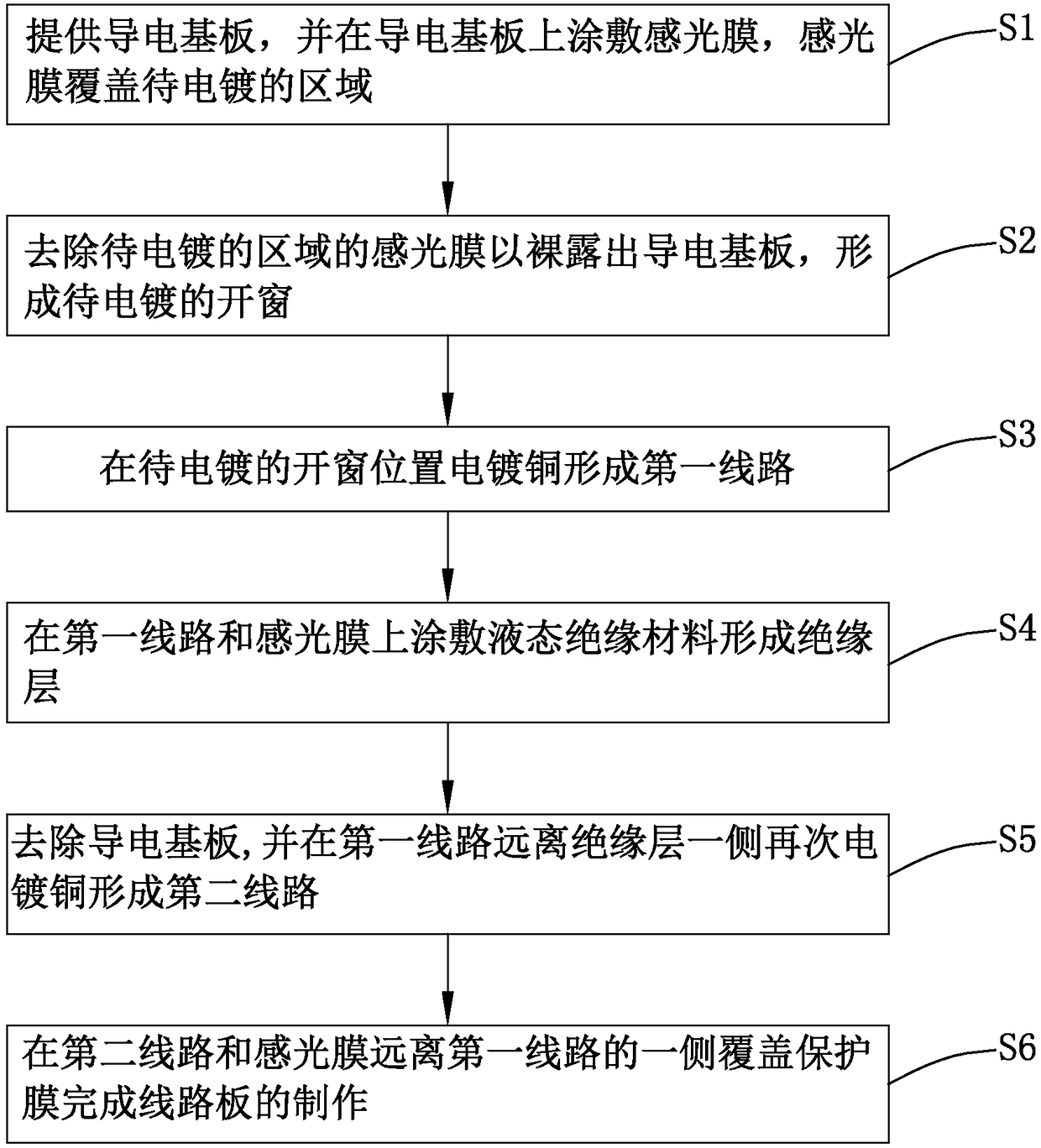
[0032] see figure 1 , the present invention provides a kind of manufacturing method of circuit board, comprises the following steps:

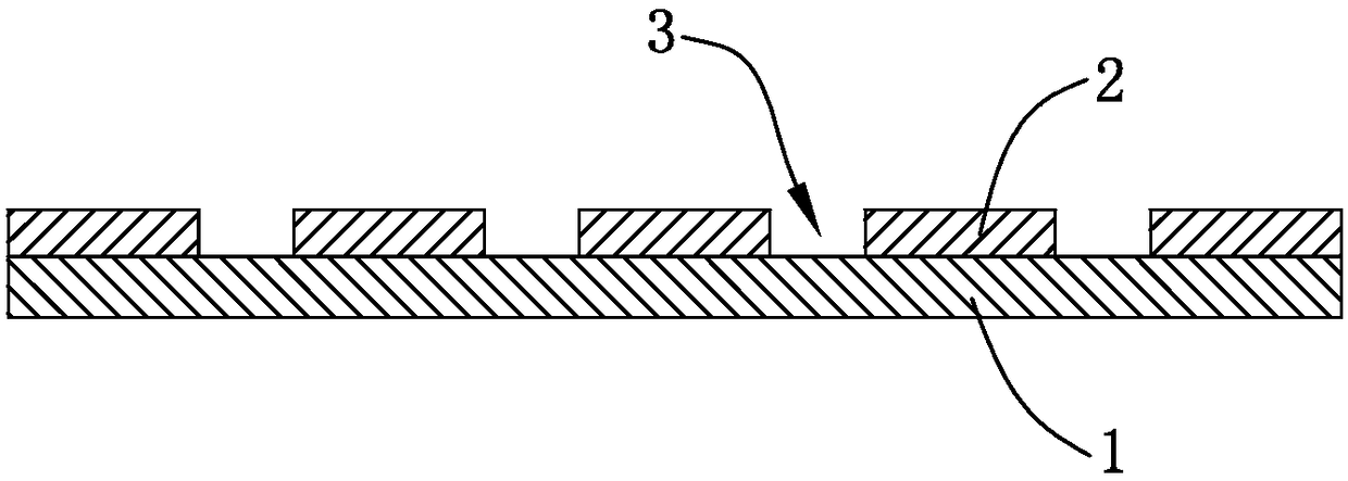
[0033] S1: Provide a conductive substrate 1, and coat a photosensitive film 2 on the conductive substrate 1. The photosensitive film 2 covers the area to be electroplated. For details, see figure 2 shown;

[0034] The conductive substrate 1 is made of conductive materials, preferably, the conductive substrate 1 is a mirror steel plate. The surface of the conductive substrate 1 can be plated with a copper layer by electroplating, and the copper layer can be peeled off the surface smoothly.

[0035] Specifically, under a yellow light environment, the photosensitive film 2 with a required thickness is pressed onto the light surface of the conductive substrate 1 under a first specified condition, and the first specified condition includes:

[0036] Temperature 65~120℃;

[0037] Pressure 1~6Kg / cm 2 ;

[0038] Speed ​​1~5m / min.

[0039] The p...

Embodiment 2

[0058] The invention provides a method for manufacturing a circuit board.

[0059] The difference between this embodiment and Embodiment 1 is that:

[0060] S2': removing the photosensitive film 2' in the area to be electroplated to expose the conductive substrate 1', forming an open window 3' to be electroplated;

[0061] Concrete, described step S2' comprises:

[0062] Bake at high temperature to fully cure the photosensitive film 2'.

[0063] Removing the photosensitive film 2' of the region to be electroplated by laser ablation;

[0064] Plasma cleaning is performed to expose the conductive substrate 1' to form an open window 3' to be electroplated.

[0065] At the same time, the present invention also provides a circuit board manufactured by applying the method for manufacturing the circuit board.

[0066] Compared with the related art, the photosensitive film 2 in the circuit board manufacturing method of the present invention is made of PI, LCP or PEN material, and ...


PUM


Abstract

The invention provides a circuit board manufacturing method and a circuit board manufactured by adopting the circuit board manufacturing method. The circuit board manufacturing method includes steps of providing a conducting substrate and coating the conducting substrate with a photosensitive film which covers a to-be-electroplated area; removing the photosensitive film covering the to-be-electroplated area so as to expose the conducting substrate, and forming a to-be-electroplated window; forming a first circuit in the position of the to-be-electroplated window through copper electroplating;coating the first circuit and the photosensitive film with liquid insulation material so as to form an insulation layer; removing the conducting substrate and forming a second circuit on a side of thefirst circuit away from the insulation layer through copper electroplating; covering the second circuit with a protection film so as to complete manufacture of the circuit board. According to the invention, PI, LCP or PEN material is adopted as a mask and mask removal is not acquired after pattern electroplating, so that the line distance of a circuit obtained after electroplating is reduced andthe copper coating thickness is increased.

Description

technical field [0001] The invention relates to the field of circuit board printing, in particular to a method for manufacturing a circuit board and a circuit board manufactured by using the method for manufacturing a circuit board. Background technique [0002] The current electronic products are rapidly developing in the direction of "short, small, light, and thin". The demand for multi-functional and high-performance electronic products continues to increase, which promotes the continuous reduction in the size of circuit boards and increasingly fine wiring. In this environment, the semi-additive process (Semi-Additive Process, SAP) and the modified semi-additive process (Modified Semi-Additive Process, M-SAP) came into being and are widely used in the circuit board printing industry. [0003] However, in the manufacturing process of the circuit board of the related art, after the SAP process adopts the mask to expose the circuit pattern, the method for directly electropla...

Claims


Application Information

Patent Timeline
IPC IPC(8): H05K3/18
CPCH05K3/18H05K2203/052
Inventor 周礼义朱晓龙
Owner AAC TECH PTE LTD
Learn More