Locator and transmitter calibration system

a technology of transmitter and locator, which is applied in the field of underground utility locator receiver and transmitter, can solve the problems of inaccurate creeping into the locating process, and achieve the effect of reducing signal strength and quick field check and calibration of locators

Active Publication Date: 2014-01-21
SEESCAN
View PDF14 Cites 56 Cited by
  • Summary
  • Abstract
  • Description
  • Claims
  • Application Information

AI Technical Summary

Benefits of technology

[0008]Another aspect of the present invention allows the rotary calibration to be performed without automation by a manual operator reading the locator screen in order to do a rapid field check and calibration of the locator.
[0009]Another aspect of the present invention is the ability to rigidly situate a locator along a vertical line perpendicular to the horizontal 4-fold symmetry axis of the field in such a...

Problems solved by technology

The majority of locating instruments use electro-mechanical elements in their circuits, such as potentiometers...

Method used


Image

  • Locator and transmitter calibration system
  • Locator and transmitter calibration system
  • Locator and transmitter calibration system

Examples


Embodiment Construction

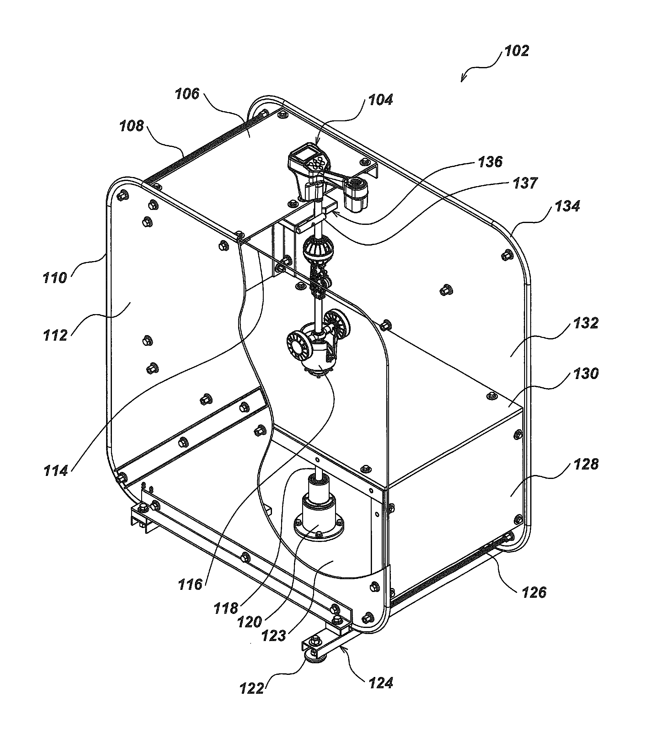
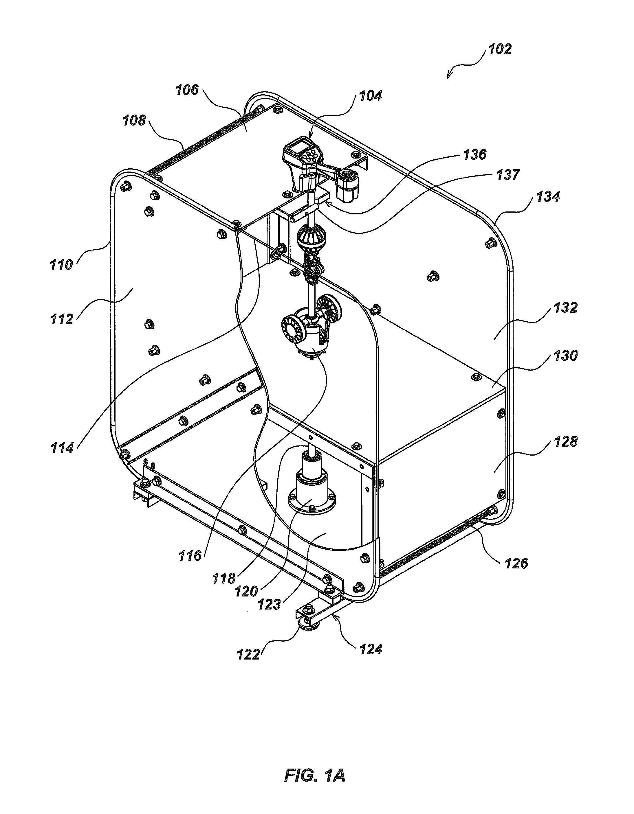
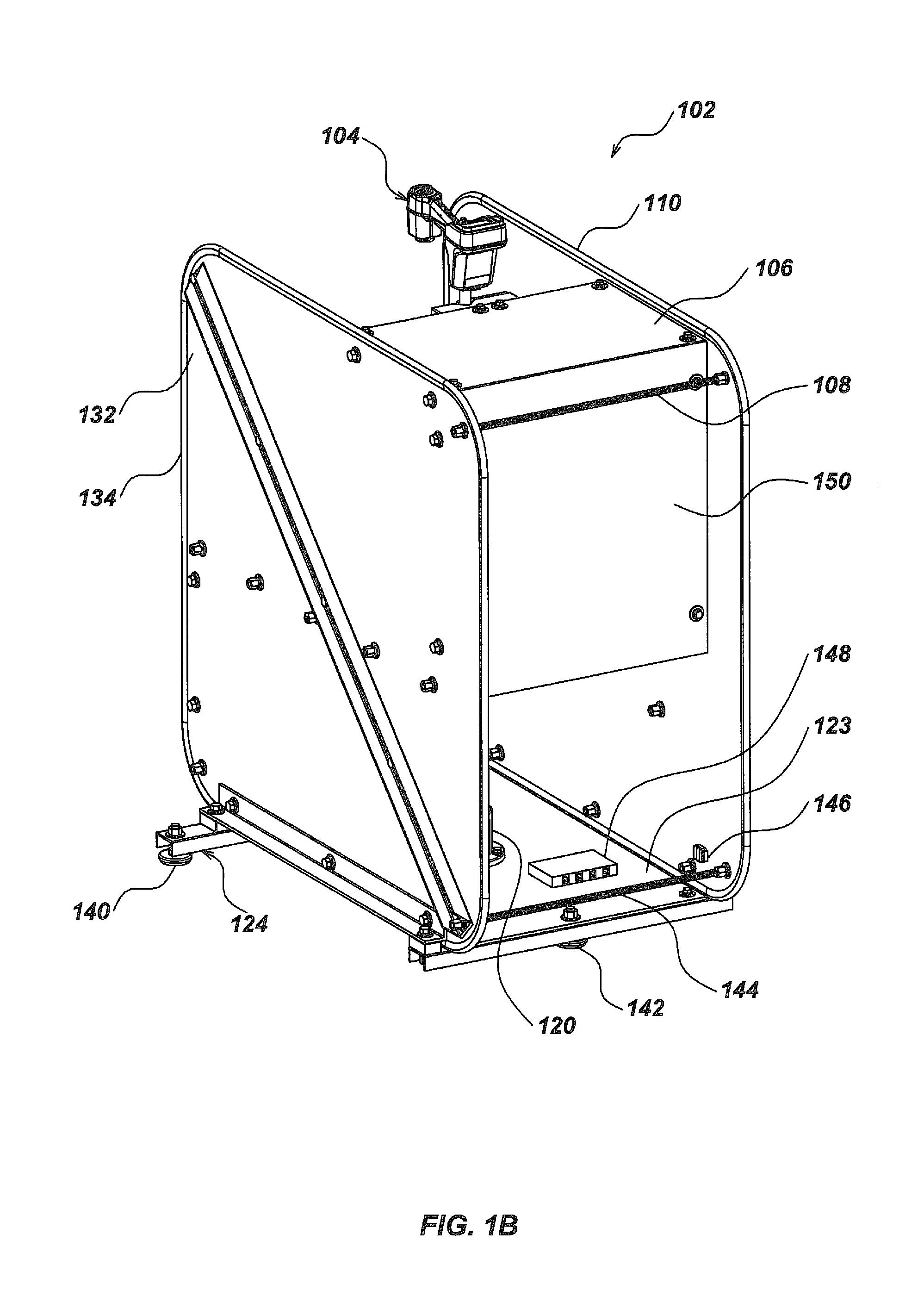
[0020]Referring to FIG. 1A, a calibration system 102 comprises a rigid calibrator frame or assembly including two side panels 112, 132 around each of which are wound the windings (e.g., 114) of the Helmholtz coil (one shown) covered by protective bumpers 110, 134. A single turn of copper tape is used for each winding in this preferred embodiment. The calibrator assembly itself comprises side panels 112, 132, a platform 130, a front lower panel 128, a lower floor 123, and top panel 106. The panels assembled on a frame 124 of joined members with three height-adjustable foot pads for leveling the system. (Only foot pad 122 is shown in this view.) The calibrator assembly is strengthened and given additional rigidity by a number of threaded stiffening rods 108 and 126, which hold opposing sides together. Panels, threaded rods, nuts, and bolts are non-magnetic and electrically insulating fiber reinforced plastics. Suitable fibers are glass and Kevlar. Suitable plastics are rigid epoxies, ...


PUM


Abstract

A framework encloses a stepper motor, mounting structure, and circuitry for use in calibrating the responses of utility locators or the precise frequency outputs of locating transmitters, and associated tilt, directional, angle, and gradient sensors. The framework contains two Helmholtz or similar field windings embedded in its sides to achieve maximum accuracy in calibration of locating instruments, such that a locator may be precisely situated within the uniform field of the windings for calibration measurement or testing. Calibration and testing may be done manually or by automated means.

Description

CROSS-REFERENCE TO RELATED APPLICATION[0001]This application claims the benefit of the filing date of the similarly entitled U.S. Provisional Patent Application Ser. No. 60 / 912,517 filed Apr. 18, 2007, of Mark S. Olsson et al., the entire disclosure of which is hereby incorporated by reference. This application is a continuation of co-pending U.S. patent application Ser. No. 12 / 103,971 filed Apr. 16, 2008, and is also a continuation-in-part of co-pending U.S. patent application Ser. No. 12 / 780,311 filed May 14, 2010, which was a division of U.S. patent application Ser. No. 12 / 243,191 filed Oct. 1, 2008, now U.S. Pat. No. 7,733,077, which was a continuation of U.S. patent application Ser. No. 11 / 970,818 filed Jan. 8, 2008, now U.S. Pat. No. 7,443,154, which was a division of U.S. patent application Ser. No. 10 / 956,328 filed Oct. 1, 2004, now U.S. Pat. No. 7,336,078, which in turn claimed benefit of U.S. Provisional Patent Application Ser. No. 60 / 508,723 filed Oct. 4, 2003.FIELD OF TH...

Claims


Application Information

Patent Timeline
IPC IPC(8): G01C19/00
CPCG01V3/12E21B47/02224G01V13/00G01C19/00E21B47/09E21B47/0232
Inventor OLSSON, MARK S.MARTIN, MICHAEL J.CODUTI, ANTHONY L.
Owner SEESCAN
Why Eureka
Try Eureka