Linear motor

a linear motor and motor stop technology, applied in the direction of motor/generator/converter stopper, motor control, dynamo-electric converter, etc., can solve the problem of insufficient effort to accurately, and achieve the effect of improving the controllability of a linear motor

Inactive Publication Date: 2014-02-04
GK BRIDGE 1
View PDF6 Cites 17 Cited by
  • Summary
  • Abstract
  • Description
  • Claims
  • Application Information

AI Technical Summary

Benefits of technology

[0007]According to the linear motor, since the plural magnetic detector devices detect the magnetic flux radially extending in the direction perpendicular to the arrangement direction of the permanent magnets in the magnet row, the detection accuracy of the changes of the magnetic flux by the plural magnetic detector devices is improved. Further, since the plural magnetic detector devices output the signal waveforms at the phases equal to the phases of the waveforms of the back electromotive forces generated in the electromagnetic coils for the respective phases with the movement of the magnet row, the control of the movement of the slider unit may be executed more appropriately and the controllability of the linear motor is improved.Application Example 2
[0011]According to the linear motor, the electromagnetic coils for three phases may be controlled based on the signals for three phases output from the plural magnetic detector devices. Further, the signals for three phases output by the plural magnetic detector devices are transformed into the signals for two phases corresponding to the position of the magnet row, and thereby, position detection of the slider unit becomes easier. Therefore, the controllability of the linear motor is further improved.Application Example 4
[0013]According to the linear motor, the magnetic efficiency of the electromagnetic coils is improved by the back yoke and the generation region of eddy currents is divided by the slits, and thereby, eddy-current loss in the back yoke is reduced.

Problems solved by technology

However, in the past, it has not been sufficient to make efforts to accurately detect the change of magnetic flux and improve the controllability of the linear motor.

Method used


Image

  • Linear motor
  • Linear motor
  • Linear motor

Examples


first embodiment

A. First Embodiment

A1. Configuration of Linear Motor

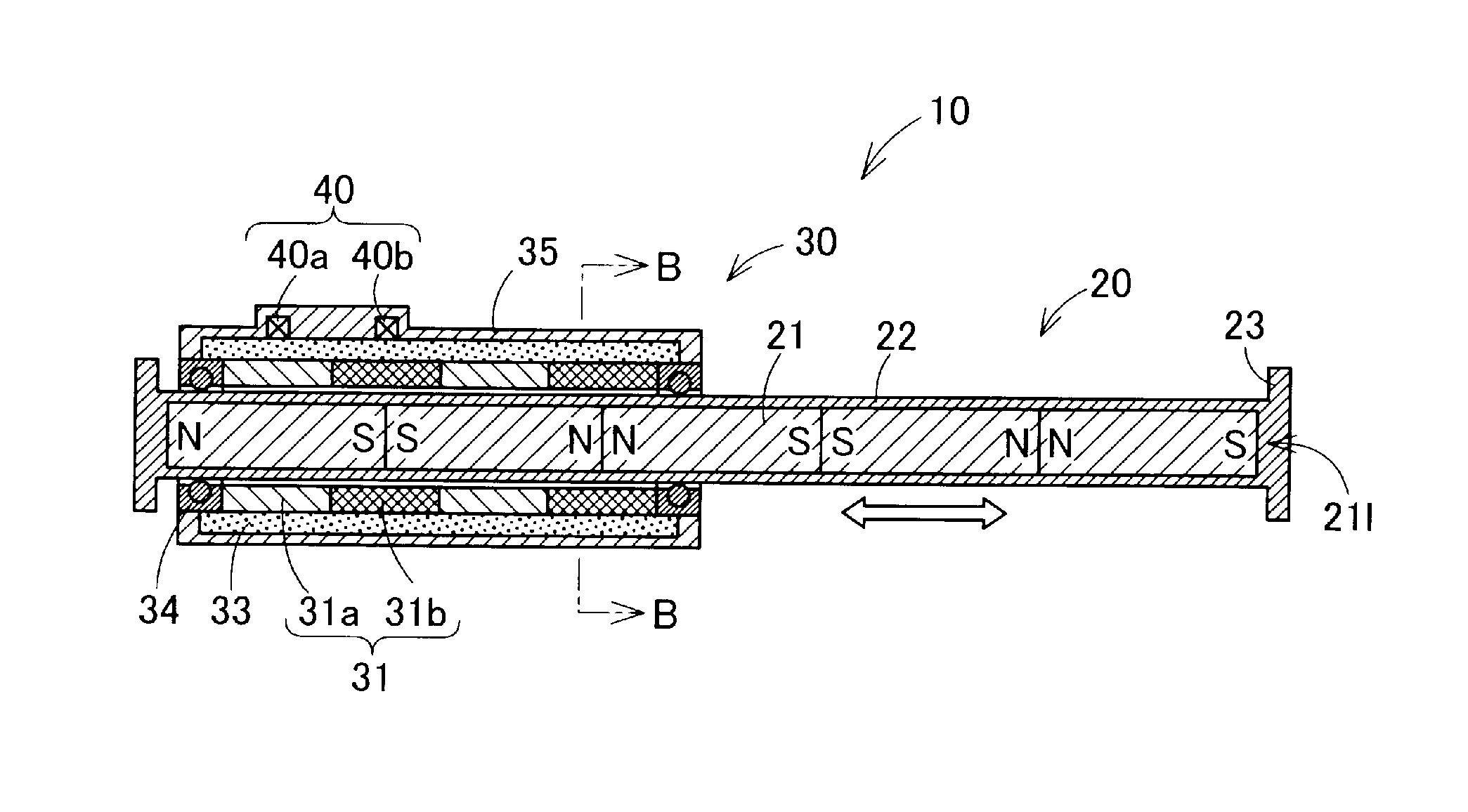
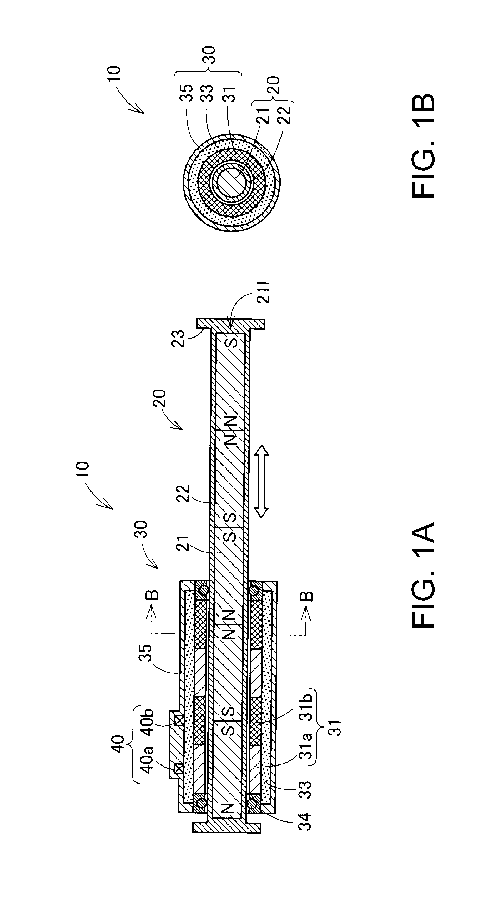
[0047]FIGS. 1A and 1B are schematic diagrams showing a configuration of a linear motor 10 as one embodiment of the invention. FIG. 1A is a schematic sectional view of the linear motor 10 seen from the side surface side. FIG. 1B is a schematic sectional view of the linear motor 10 along B-B section.

[0048]The linear motor 10 includes a movable element 20 in a nearly straight rod shape (also referred to as “slider 20”) and a stator 30 in a nearly cylindrical shape. The slider 20 is inserted into the stator 30 to reciprocate along the center axis direction of itself (shown by a hollow arrow).

[0049]The slider 20 includes a casing 22 in a nearly cylindrical shape with closed ends and a magnet row 211 contained within the casing 22. The magnet row 211 is a magnet device in which plural permanent magnets 21 are arranged in series so that the same poles are opposed to each other. Note that, in FIG. 1A, “N”, “S” indicating an N-pole and an S...

second embodiment

B. Second Embodiment

B1. Configuration of Linear Motor

[0177]FIGS. 24A, 24B are schematic diagrams showing a configuration of a linear motor 10C as the second embodiment of the invention. FIGS. 24A, 24B are nearly the same as FIGS. 1A and 1B except that C-phase electromagnetic coils 31c and a C-phase position detection sensor 40c are provided. In the stator 30 of the linear motor 10C, two sets of electromagnetic coils 31a, 31b, 31c for three phases are arranged in series. Further, in the stator 30 of the linear motor 10C, position detection sensors40a, 40b, 40c corresponding to the respective phases are provided on the outer circumferences of the electromagnetic coils 31a, 31b, 31c for three phases on the left of the paper.

B2. Control of Linear Motor

[0178]FIG. 25 is a block diagram showing a configuration of a control unit 100C controlling the linear motor 10C of the second embodiment. FIG. 25 is nearly the same as FIG. 6 except that a C-phase drive control part 113 and a C-phase driv...

modified example 1

C1. Modified Example 1

[0199]In the embodiments, the linear motors 10, 10A, 10B, 10C have included the electromagnetic coils 31 for two phases or three phases and position detection sensors 40 for two or three phases. However, a linear motor may further include electromagnetic coils 31 for plural phases and plural position detection sensors 40 for the respective phases of the electromagnetic coils 31.


PUM


Abstract

A linear motor includes a slider unit having a magnet row in which plural permanent magnets are arranged in series so that the same poles are opposed to each other, a stator unit including electromagnetic coils for plural phases arranged along a movement direction of the slider unit, and plural magnetic detector devices, wherein the plural magnetic detector devices are provided in response to the phases of the electromagnetic coils for plural phases and detect magnetic flux radially extending in a direction perpendicular to the arrangement direction of the permanent magnets at boundaries between the permanent magnets of the magnet row and output signal waveforms for plural phases at phases equal to phases of waveforms of back electromotive forces generated in the respective electromagnetic coils for plural phases when the magnet row moves.

Description

BACKGROUND[0001]1. Technical Field[0002]The present invention relates to a linear motor.[0003]2. Related Art[0004]As a motor, a linear motor that linearly moves a movable element relative to a stator using electromagnetic force is known (Patent Document 1 (JP-A-2008-289344). In the linear motor, the movement of the movable element is controlled by detecting the change of magnetic flux due to movement of the movable element and controlling a magnetic field generated by an electromagnetic coil based on the change of magnetic flux. However, in the past, it has not been sufficient to make efforts to accurately detect the change of magnetic flux and improve the controllability of the linear motor.SUMMARY[0005]An advantage of some aspects of the invention is to provide a technology of improving the controllability of a linear motor.Application Example 1[0006]This application example of the invention is directed to a linear motor including a slider unit having a magnet row in which plural ...

Claims


Application Information

Patent Timeline
Patent Type & Authority Patents(United States)
IPC IPC(8): H02K11/00H02K41/02
CPCH02P6/182H02K29/08H02K41/031H02K11/0021H02P6/006H02K11/215
Inventor TAKEUCHI, KESATOSHI
Owner GK BRIDGE 1
Why Eureka
Try Eureka