Method for collimating to an off-center examination sub-object

a sub-object and collimation technology, applied in the field of collimation to an off-center examination sub-object, can solve the problems of terns of resolution and scan field disadvantages, and achieve the effect of precise collimation and loss of important information

Inactive Publication Date: 2014-02-04
SIEMENS HEALTHCARE GMBH
View PDF4 Cites 1 Cited by
  • Summary
  • Abstract
  • Description
  • Claims
  • Application Information

AI Technical Summary

Benefits of technology

[0013]An advantage of the method according to the invention is that precise off-center collimation achieves a reduction in the radiation dose for the examination subject by avoiding unnecessary radiation. This is on the one hand more healthy for the patient and, on the other, can be used for more precise diagnosis. In addition, it eliminates time-consuming central positioning of the sub-object, necessitating the repositioning of the examination subject (the patient). Imaging now becomes possible in cases where the sub-object cannot be centrally positioned for anatomical reasons. The selective collimation can also reduce the radiation exposure for the physician as there is less stray radiation.
[0015]The collimator advantageously has different elements, known as collimator jaws, and the collimator elements are individually controlled and positioned for collimation, thereby enabling particularly precise collimation to the sub-object.
[0016]According to another embodiment of the invention, the smallest image section which completely renders the sub-object is collimated to. This prevents portions of the sub-object from being truncated in the image, thereby losing important information; on the other hand, as little additional, unnecessary information as possible is acquired.
[0017]According to a first alternative, the collimation is carried out simply for a stationary angiographic imaging system. Any number of X-ray images can then be taken, as long as no movement of the gantry or examination subject takes place. This is particularly suitable for simple fluoroscopic operation of the X-ray diagnostic apparatus.

Problems solved by technology

In 3D imaging, however, the conventional CT machines are still superior in terms of low-contrast resolution and imaging speed; in 2D imaging, on other hand, they have disadvantages in terns of the resolution and scan field.

Method used


Image

  • Method for collimating to an off-center examination sub-object
  • Method for collimating to an off-center examination sub-object
  • Method for collimating to an off-center examination sub-object

Examples


Embodiment Construction

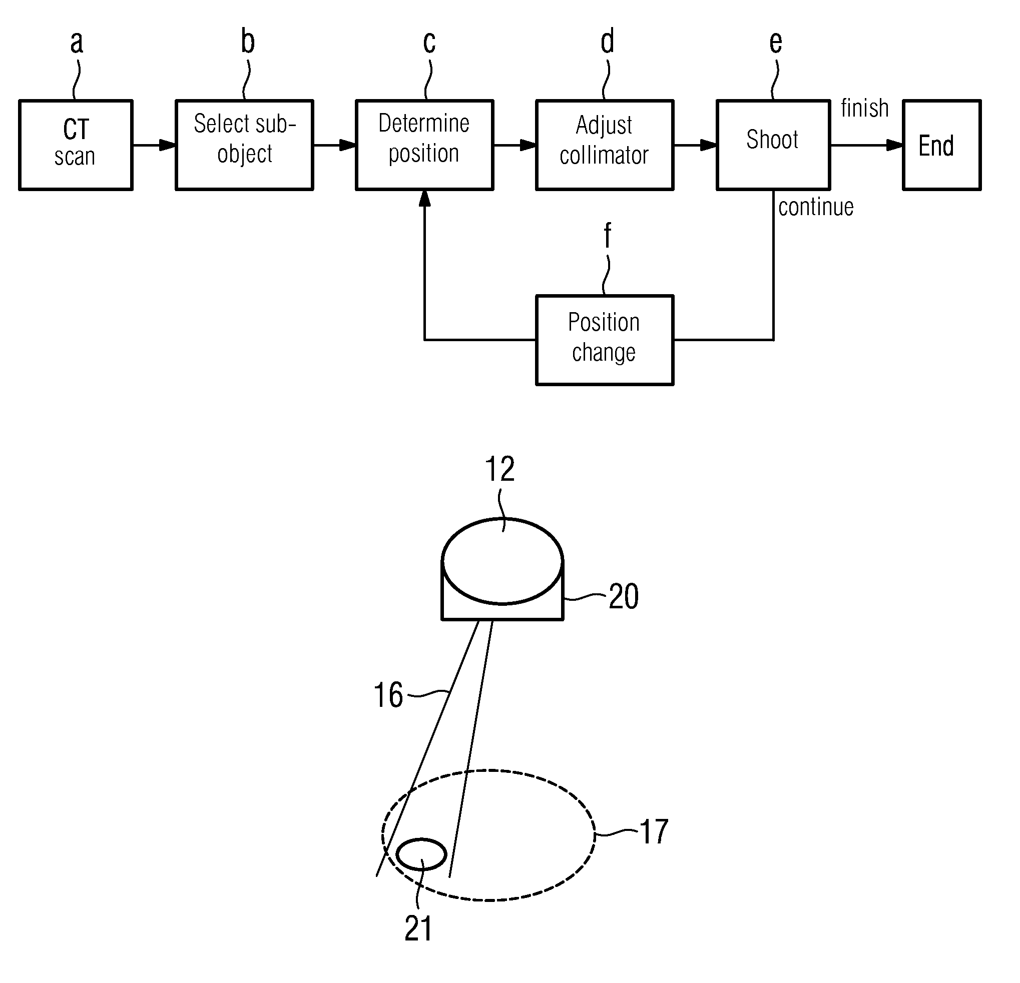
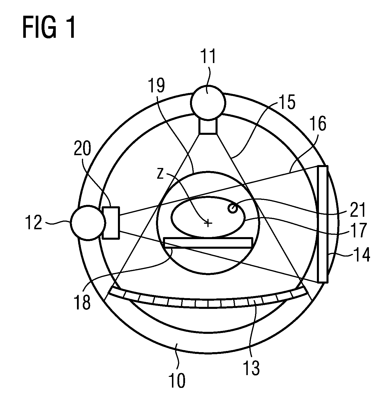
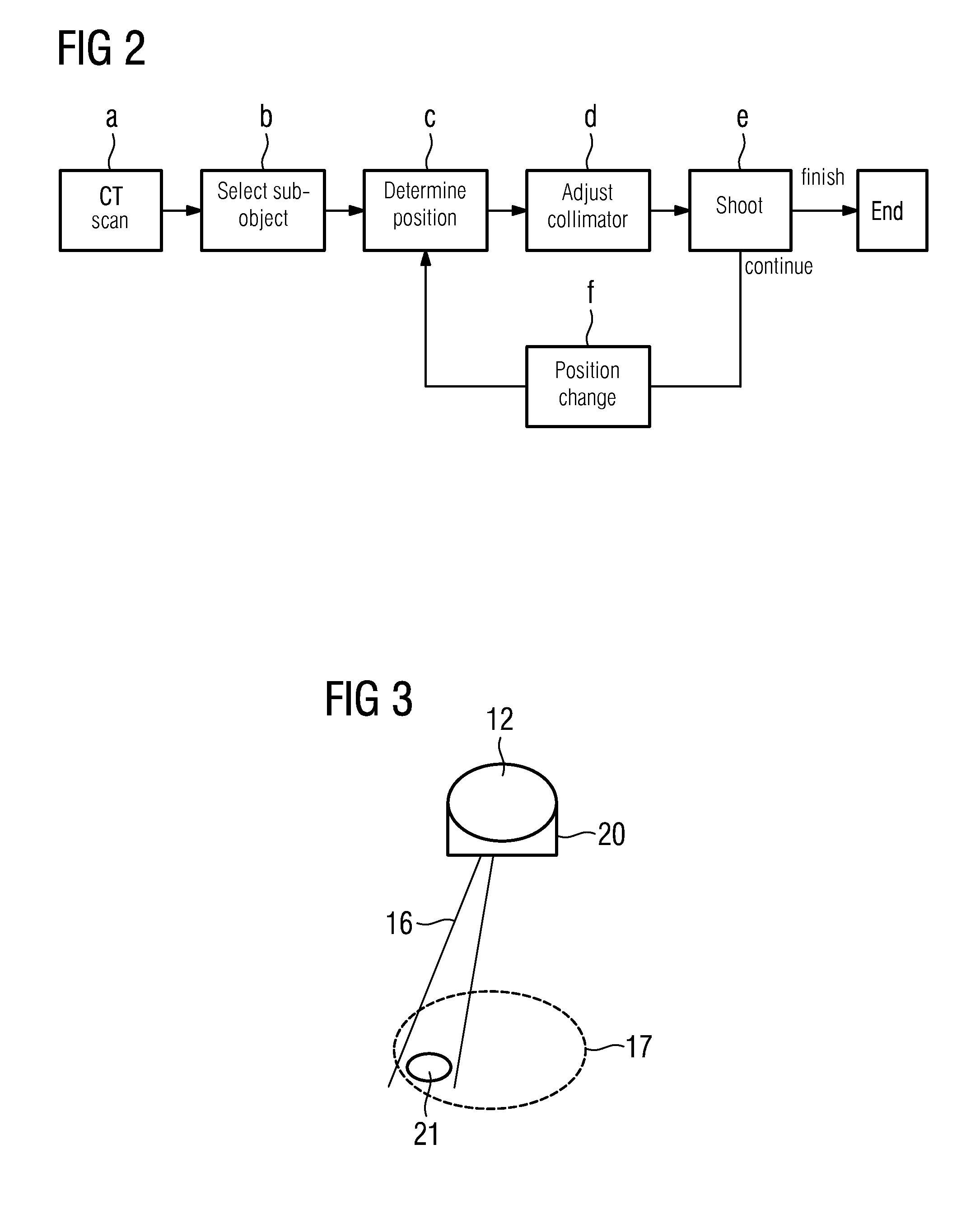
[0023]A known X-ray diagnostic apparatus shown in FIG. 1 contains, in a gantry 10, a computed tomography (CT) imaging system with a first X-ray source 11 and a CT X-ray detector 13, and an angiographic imaging system with a second X-ray source 12 and a second flat panel X-ray detector 14. In the case of the CT imaging system, the first X-ray source 11 emits a fan beam 19 and the CT X-ray detector 13 is curved and composed of a number of individual detectors (e.g. 512). To scan an examination subject 17 disposed on a patient table 18, the CT imaging system rotates around the examination subject 17 through 360° by means of the gantry 10; the data set acquired can be reconstructed into a 3D volume image.

[0024]The angiographic imaging system has a second X-ray source 12 and a flat panel X-ray detector 14; the second X-ray source emits a conical X-ray beam 16 onto the flat panel X-ray detector 14. Between the first perpendicular bisector from the first X-ray source 11 onto the CT X-ray d...


PUM


Abstract

A method is proposed for collimating an off-center sub-object of an examination subject by a collimator of an X-ray diagnostic apparatus. The apparatus has a computed tomography imaging system having a first X-ray source and a computed tomography X-ray detector disposed opposite the first X-ray source having a number of individual detectors and an angiographic imaging system having a second X-ray source offset to the first X-ray source and a flat panel X-ray detector disposed opposite the second X-ray source with matrix shaped pixel elements. A 3D image of the subject is taken by the CT imaging system. The off-center sub-object is selected based on the 3D image. The position of the sub-object is determined for a shooting position of the angiographic imaging system according to the fixed relative disposition between the angiographic imaging system and the CT imaging system. The collimator is adjusted accordingly for collimating the off-center section.

Description

CROSS REFERENCE TO RELATED APPLICATIONS[0001]This application claims priority of German application No. 10 2010 040 812.3 filed Sep. 15, 2010, which is incorporated by reference herein in its entirety.FIELD OF THE INVENTION[0002]The invention relates to a method for collimating to an off-center examination sub-object by means of an imaging system of an X-ray diagnostic apparatus having a rotatable gantry.BACKGROUND OF THE INVENTION[0003]X-ray diagnostic systems are standard medical imaging equipment and are used e.g. for interventional therapy. Angiographic systems, generally C-arm X-ray systems, are typically used for monitoring vascular and heart disease therapy and for minimally invasive tumor therapy. Their flat-panel X-ray detectors with pixel elements disposed in a matrix provide a very high local resolution (pixel size generally about 150 μm) and can be used for both for 2D and 3D imaging (Siemens DynaCT). In 3D imaging, however, the conventional CT machines are still superio...

Claims


Application Information

Patent Timeline
Patent Type & Authority Patents(United States)
IPC IPC(8): A61B6/00
CPCA61B6/4014A61B6/488A61B6/504A61B6/032A61B6/08A61B6/469A61B6/5235A61B6/463A61B6/00A61B6/545A61B6/06
Inventor KLINGENBECK, KLAUS
Owner SIEMENS HEALTHCARE GMBH
Why Eureka
Try Eureka