Unlock instant, AI-driven research and patent intelligence for your innovation.

Frame processing apparatus, optical receiving apparatus, optical transceiving apparatus, optical transmission system, and frame processing controlling method

a frame processing and control method technology, applied in the field of frame processing apparatus, can solve problems such as increasing power consumption

Inactive Publication Date: 2014-02-11
FUJITSU LTD
View PDF17 Cites 2 Cited by
  • Summary
  • Abstract
  • Description
  • Claims
  • Application Information

AI Technical Summary

Benefits of technology

This patent describes a frame processing apparatus that can switch between different error processing modes based on the monitoring results of signal quality. The apparatus can include a controlling unit that receives the monitoring results and switches between different error processing modes accordingly. This allows for efficient error correction processing. The invention aims to improve the reliability and quality of optical signals in optical transmission systems.

Problems solved by technology

Because of this, the circuit module of the error correction processing has a tendency such that the larger the gate scale, the larger the power consumption.

Method used


Image

  • Frame processing apparatus, optical receiving apparatus, optical transceiving apparatus, optical transmission system, and frame processing controlling method
  • Frame processing apparatus, optical receiving apparatus, optical transceiving apparatus, optical transmission system, and frame processing controlling method
  • Frame processing apparatus, optical receiving apparatus, optical transceiving apparatus, optical transmission system, and frame processing controlling method

Examples


first embodiment

[A] First Embodiment

[0031]FIG. 1 is a diagram illustrating an optical reception apparatus 10 according to a first embodiment. The optical reception apparatus 10 depicted in FIG. 1 is applicable to, for example, an optical receiver 5 constituting optical transceivers 8A and 8B in an optical transmission system 1 illustrated in FIG. 2. Here, in the optical transmission system 1 depicted in FIG. 2, a transmission path fiber 2a and an optical relay amplifier 2b are mutually connected, and one or more optical transmission apparatuses 3, which perform optical add-drop multiplexing and wavelength cross connect, are arranged on the transmission path fiber 2a.

[0032]The optical transceivers 8A and 8B, each including an optical transmitter 4 and an optical receiver 5, are coupled to the optical transmission apparatuses 3 and bi-directionally send and receive optical signals by way of the above described optical transmission apparatuses 3, the transmission path fiber 2a, and the optical relay ...

second embodiment

[B] Second Embodiment

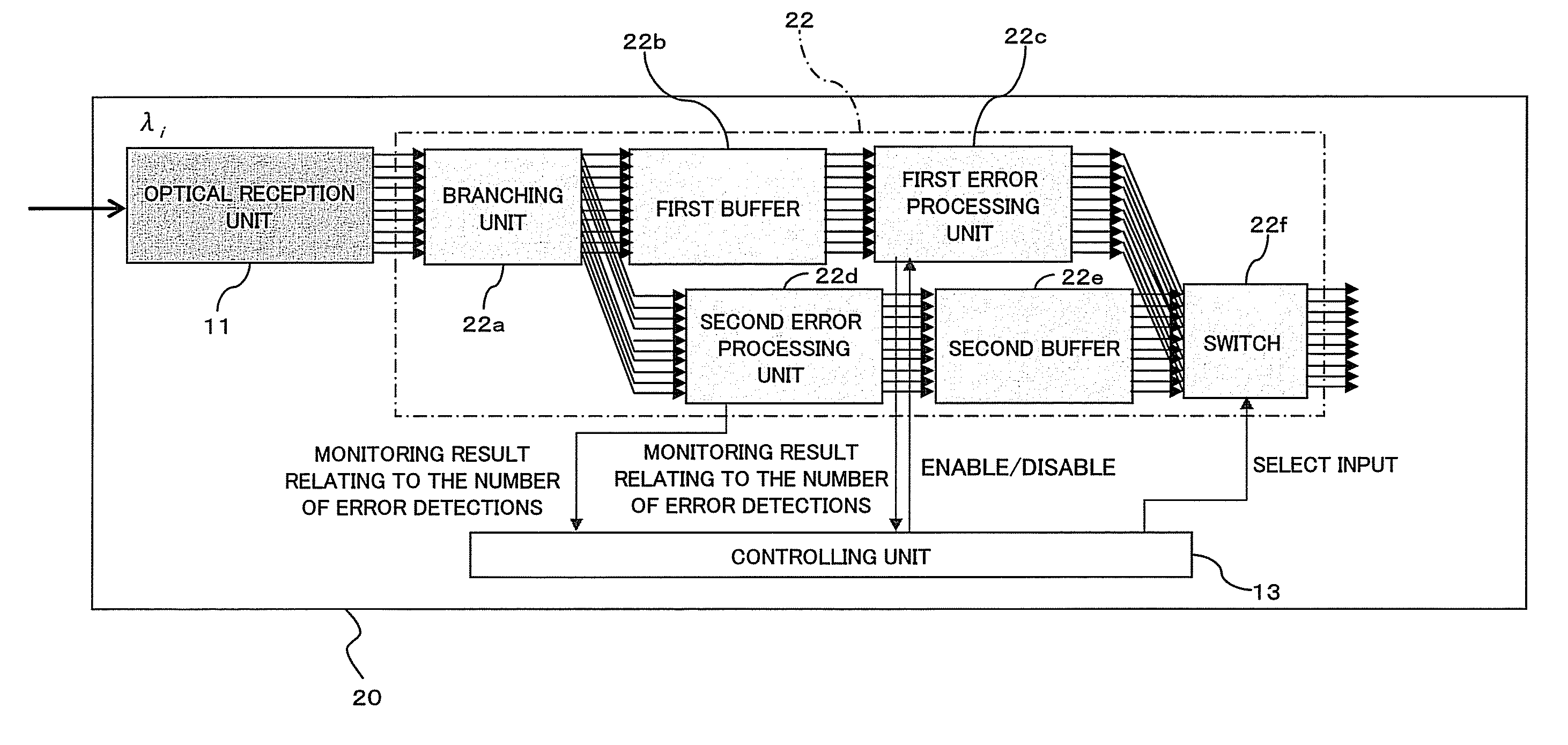
[0061]FIG. 5 is a diagram illustrating an optical reception apparatus 20 according to a second embodiment. The optical reception apparatus 20 illustrated in FIG. 5 is applicable to, for example, an optical receiver 5 in the optical transmission system 1 illustrated in FIG. 2. Here, the optical reception apparatus 20 includes not only the optical reception unit 11 and the controlling unit 13 similar to the above described first embodiment (see FIG. 1) but also a frame processing unit 22. The reception end frame processing unit (see reference character 5b of FIG. 2) includes a controlling unit 13 and the frame processing unit 22.

[0062]Further, the frame processing unit 22, which corresponds to one mode of the frame processing unit 12 according to the above described first embodiment, performs reception end frame processing including frame synchronization processing and in-frame processing such as error correction processing based on setting of the operation mode p...

third embodiment

[C] Third Embodiment

[0084]FIG. 7 is a diagram illustrating an optical transmission system 30 according to a third embodiment. In the optical transmission system 30 depicted in FIG. 7, also, an optical transmitter 31 and an optical receiver 33 are coupled by way of an optical transmission path 32 provided with the transmission path fiber and the optical relaying amplifier amplifying and relaying unit or the like similar to those depicted in FIG. 2. Further, the optical transmitter 31 and the optical receiver 33 are also connected to each other by way of the control signal propagation path 43 for transceiving a control signal. In this instance, the optical transmission path 32 in FIG. 7 pays an attention to transmission of an optical signal having a wavelength of λi corresponding to one channel. In FIG. 7, illustration of the wavelength multiplexer 6 and the wavelength demultiplexer 7 or the like is omitted.

[0085]The optical transmitter 31 includes: a transmission end frame processing...


PUM


Abstract

The technique for improving the efficiency in use of power resources while maintaining the received signal quality that satisfies the requirement during a system operation is disclosed. The frame processing apparatus disclosed in the present case includes: a frame processing unit which performs frame processing on an input signal in the designated error processing mode; and a controlling unit which receives the monitoring result relating to the signal quality of the input signal and performs switching control of the designation of the above error processing mode in the frame processing unit based on the received monitoring result.

Description

CROSS-REFERENCE TO RELATED APPLICATION(S)[0001]This application is based upon and claims the benefit of priority of the prior Japanese Patent Application No. 2008-198540, filed on Jul. 31, 2008 in Japan, the entire contents of which are incorporated herein by reference.FIELD[0002]The present invention relates to a frame processing apparatus, an optical receiving apparatus, an optical transceiving apparatus, an optical transmission system, and a frame processing controlling method.BACKGROUND[0003]As technology for supporting speeding up of information communications and long-distance transmission paths, error correction processing is well known. The error correction processing applies error correction codes in order to correct bit errors with respect to a signal that is transmitted through a transmission path and received at the reception terminal. The necessity of error correction processing is heightened by the fact that the ability of the element(s) constituting the reception appa...

Claims


Application Information

Patent Timeline
Patent Type & Authority Patents(United States)
CPCH04L43/0847H04J14/0227H04L1/20H04L1/0036H04J14/0283H04J14/0279H04L1/0053H04J14/0246H04L1/203
Inventor HOSHIDA, TAKESHIFUKUMITSU, KATSUMI
Owner FUJITSU LTD