Optical Device Structure Using GaN Substrates for Laser Applications

a technology of optical devices and substrates, applied in the direction of laser optical resonator construction, laser details, semiconductor lasers, etc., can solve the problems of inefficiency of conventional edison light bulbs, inconvenient use, and inability to meet the requirements of laser operation, so as to achieve cost-effective, simple and cost-effective effects

Active Publication Date: 2010-12-16
KYOCERA SLD LASER INC
View PDF102 Cites 261 Cited by
  • Summary
  • Abstract
  • Description
  • Claims
  • Application Information

AI Technical Summary

Benefits of technology

[0017]Benefits are achieved over pre-existing techniques using the present invention. In particular, the present invention enables a cost-effective optical device for laser applications. In a specific embodiment, the present optical device can be manufactured in a relatively simple and cost effective manner. Depending upon the embodiment, the present apparatus and method can be manufactured using conventional materials and/or methods according to one of ordinary skill in the art. The ...

Problems solved by technology

Unfortunately, drawbacks exist with the conventional Edison light bulb:
The conventional light bulb is inefficient.
The conventional light bulb is not as reliable as it could be, often failing from thermal expansion and contraction of the filament element.
Conventional light bulbs emit in all directions and are not ideal for applications requiring strong directionality or focus such as projection displays, optical data storage, or specialized directed lighting.
The Ar-ion laser had the benefit of producing highly directional and focusable light with a narrow spectral output, but the efficiency, size, weight, and cost of the lasers were undesirable.
As laser technology evolved, more efficient lamp pumped solid state laser designs were developed for the red and infrared wavelengths, but these technologies remained a challenge for blue and green lasers and blue lasers.
The resulting green and blue lasers were called “lamp pumped solid state lasers with second harmonic generation” (LPSS with SHG) ...

Method used


Image

  • Optical Device Structure Using GaN Substrates for Laser Applications
  • Optical Device Structure Using GaN Substrates for Laser Applications
  • Optical Device Structure Using GaN Substrates for Laser Applications

Examples


example

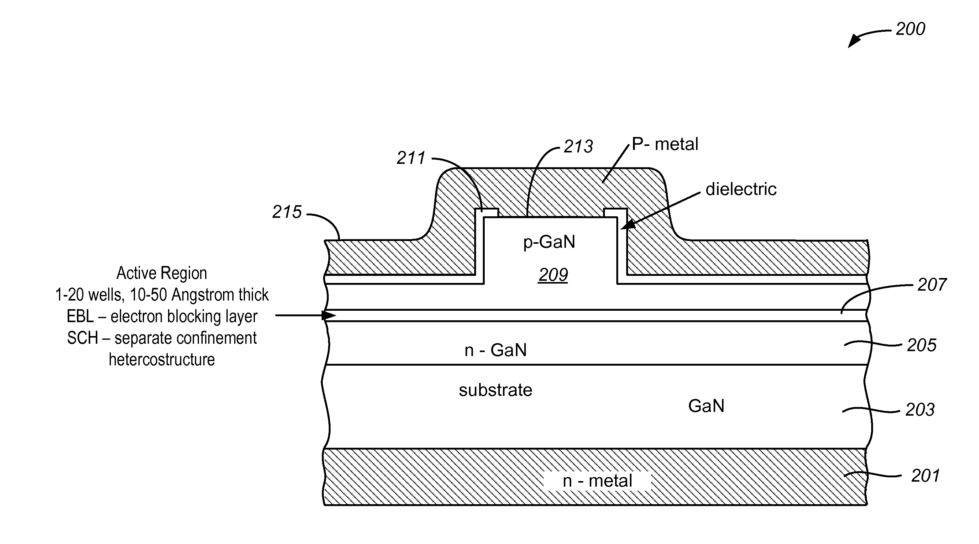
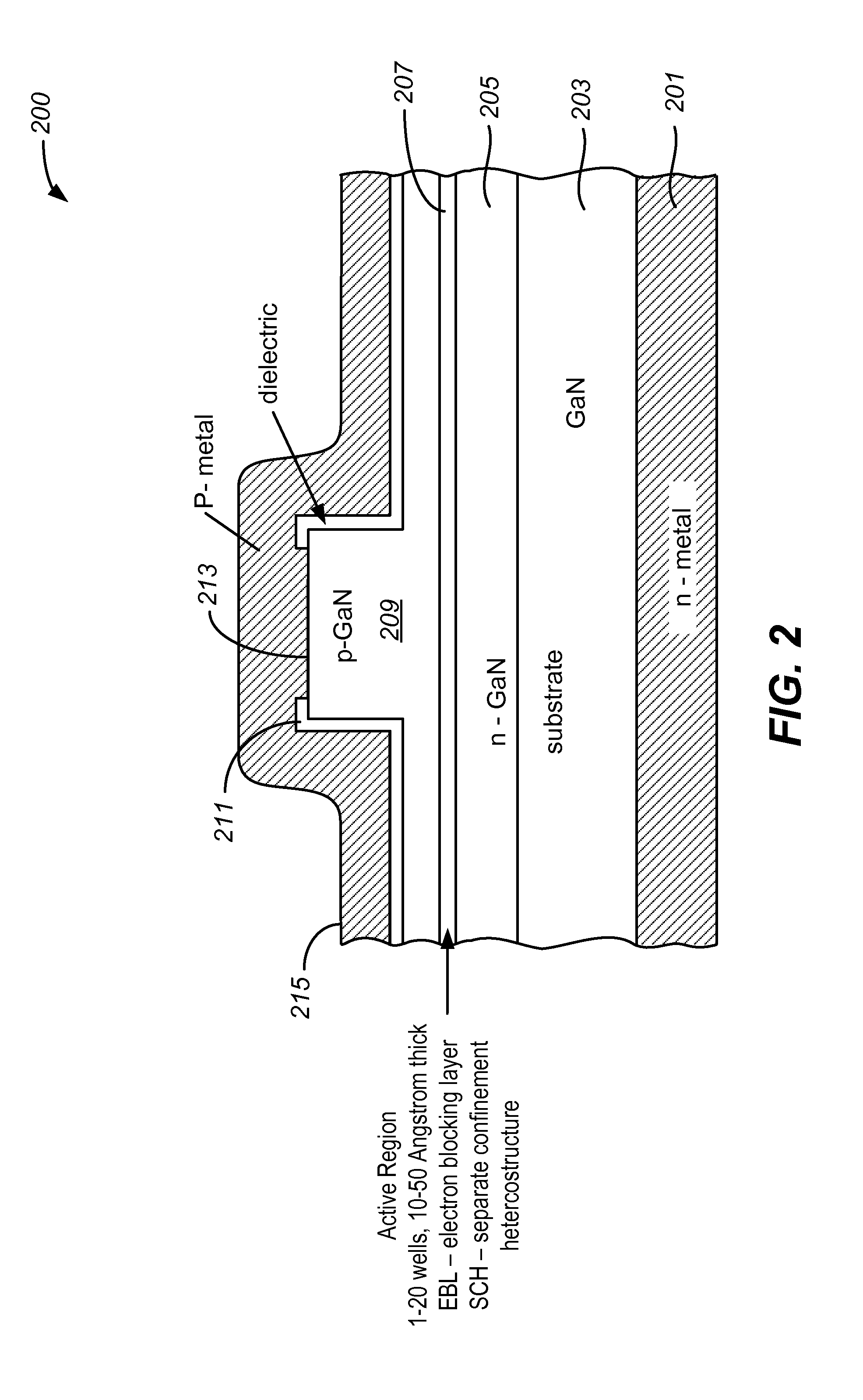
[0072]FIG. 13 is a simplified diagram illustrating a laser device according to one or more examples of the present invention. This diagram is merely an illustration and should not unduly limit the scope of the claims herein. One of ordinary skill in the art would recognize other variations, modifications, and alternatives. In this example, the optical device includes a gallium nitride substrate member having a nonpolar crystalline surface region characterized by an orientation of about 1 degree towards (000-1) and less than about 0.3 degrees towards (11-20). The bulk nitride GaN substrate comprises nitrogen and has a surface dislocation density below 1E-6 cm−2 and a surface roughness of less than 0.2 nm.

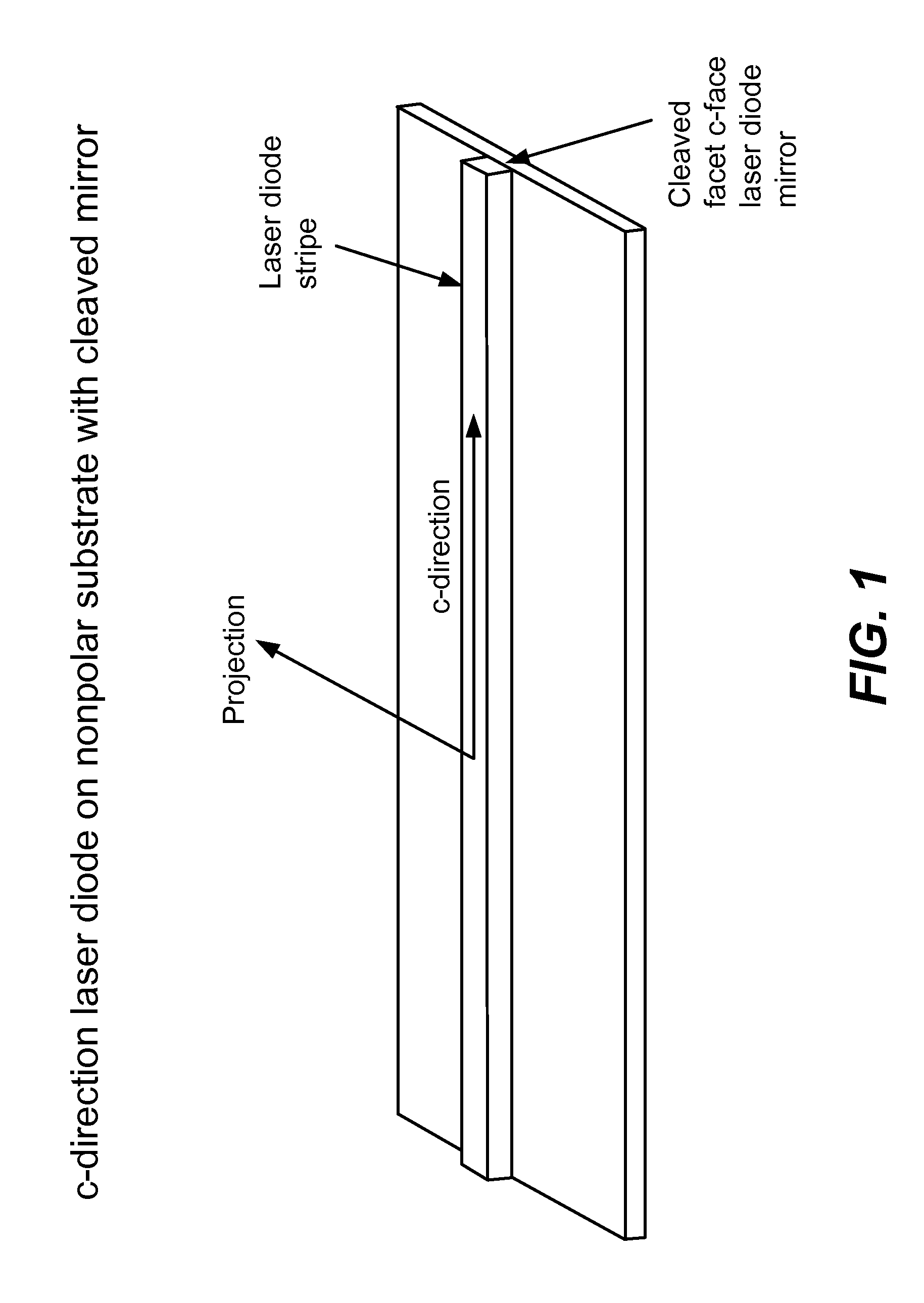
[0073]The device has a laser stripe region formed overlying a portion of the nonpolar crystalline orientation surface region. The laser stripe region is characterized by a cavity orientation is substantially parallel to the c-direction and has a first end and a second end. The device...


PUM


Abstract

An optical device includes a gallium nitride substrate member having an m-plane nonpolar crystalline surface region characterized by an orientation of about −2 degrees to about 2 degrees towards (000-1) and less than about 0.5 degrees towards (11-20). The device also has a laser stripe region formed overlying a portion of the m-plane nonpolar crystalline orientation surface region. A first cleaved c-face facet is provided on one end of the laser stripe region, and a second cleaved c-face facet is provided on the other end of the laser stripe region.

Description

CROSS-REFERENCES TO RELATED APPLICATIONS [0001]This application claims priority to U.S. Ser. No. 61 / 168,926 (Attorney Docket No. 027600-000200US) filed Apr. 13, 2009, and U.S. Ser. No. 61 / 243,502 (Attorney Docket No. 027600-001300US) filed Sep. 17, 2009, each of which is commonly assigned and hereby incorporated by reference.BACKGROUND OF THE INVENTION[0002]This invention is directed to optical devices and related methods. More particularly, the present invention provides a method and device for emitting electromagnetic radiation using nonpolar gallium containing substrates such as GaN, MN, InN, InGaN, AlGaN, and AlInGaN, and others. Merely by way of example, the invention can be applied to optical devices, lasers, light emitting diodes, solar cells, photoelectrochemical water splitting and hydrogen generation, photodetectors, integrated circuits, and transistors, among other devices.[0003]In the late 1800's, Thomas Edison invented the light bulb. The conventional light bulb, common...

Claims


Application Information

Patent Timeline
IPC IPC(8): H01S5/10H01S5/00H01L21/30
CPCH01L21/02389H01L21/02433H01L21/0254H01S5/0202H01S5/028H01S5/0287H01S5/2009H01S5/2201H01S5/3202H01S5/32341H01S5/32025
Inventor RARING, JAMES W.FEEZELL, DANIEL F.PFISTER, NICHOLAS J.SHARMA, RAJAT
Owner KYOCERA SLD LASER INC
Why Eureka
Try Eureka