

High-frequency amplifier and radio communication apparatus
a radio communication apparatus and high-frequency amplifier technology, applied in the direction of high-frequency amplifiers, one-port networks, gain control, etc., can solve the problems of difficult to determine an optimum operating point, the size of the circuit and the power consumption increase, and the operation condition of the high-frequency amplifier cannot be sustained in a stable state throughout a wide frequency band. achieve the effect of preventing the size of the circuit and the power consumption from increasing, widening the dynamic range, and maintaining the dependen
Active Publication Date: 2014-02-11
SATURN LICENSING LLC
View PDF8 Cites 5 Cited by
- Summary
- Abstract
- Description
- Claims
- Application Information
AI Technical Summary
Benefits of technology
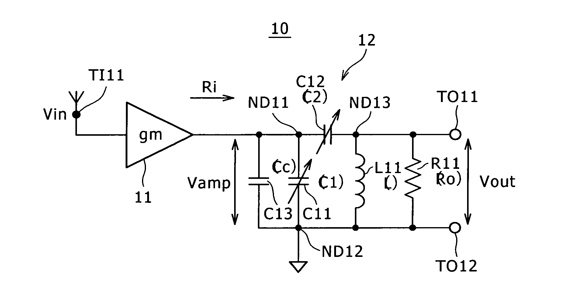
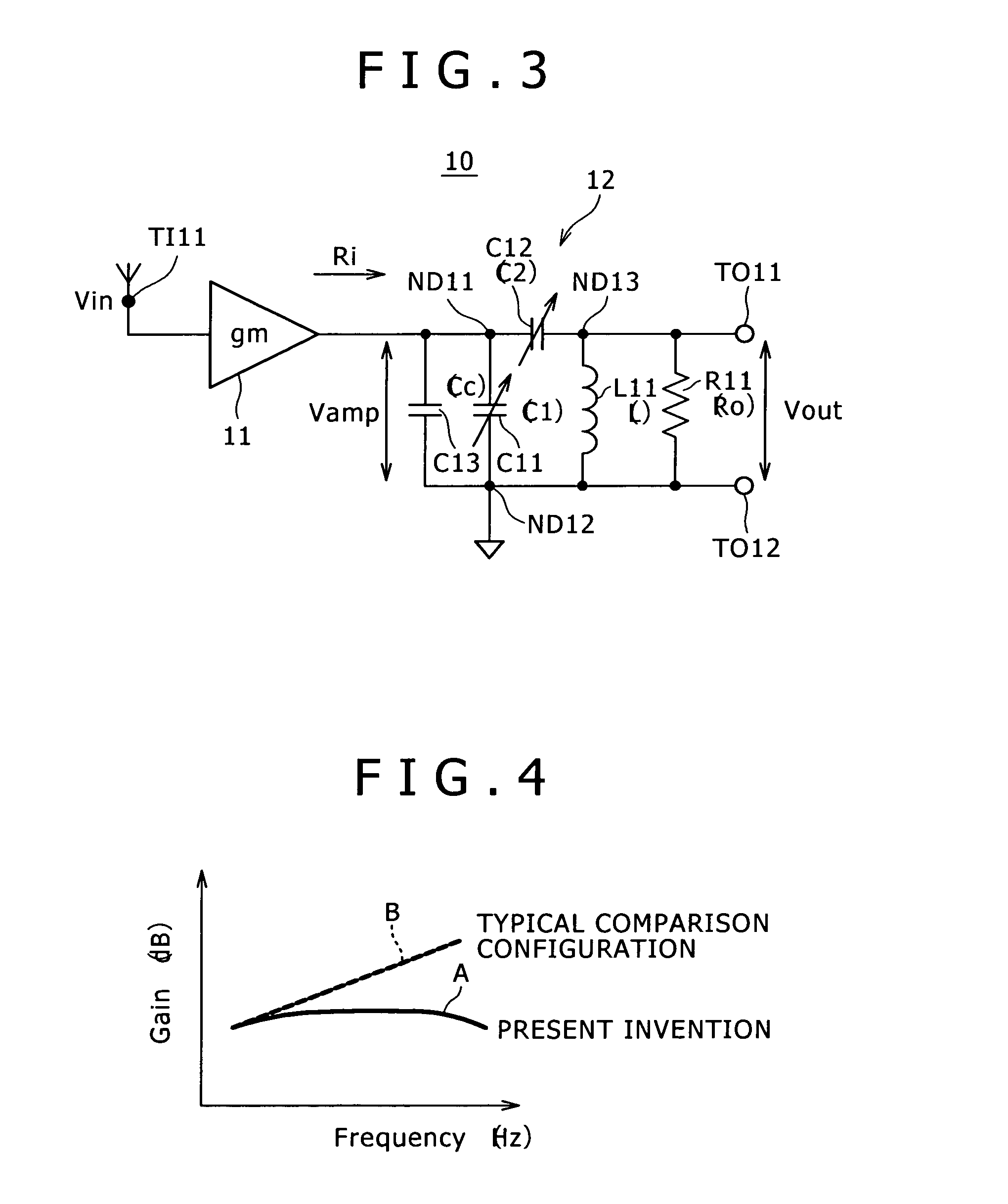
The present invention describes a high-frequency amplifier that can prevent circuit size and power consumption from increasing, while suppressing the amplitude of a signal at the output node. This amplifier also wides the dynamic range and sustains the dependence of its gain on frequency in a stable state. Additionally, a radio communication apparatus that utilizes this amplifier is also described. The technical effects of this invention are improved efficiency and reduced size and power consumption of the amplifier, as well as increased dynamic range and stable frequency response.
Problems solved by technology
Thus, the operating condition of the high-frequency amplifier 1 cannot be sustained in a stable state throughout a wide frequency band.
As a result, the characteristics representing dependence of the SNR and the distortion performance on the frequency show increased dependence so that it is difficult to determine an optimum operating point.
With this method, however, the size of the circuit and the power consumption increase.
In addition, this method has bad effects caused by typically increased noises and the like.
Thus, the amplitude of a signal appearing at the output node of the amplification section increases so that a limit is unavoidably imposed on the dynamic range due to deterioration of the distortion performance.
Method used
View moreImage
Smart ImageViewing Examples

Examples
first embodiment (
1. First Embodiment (First Typical Configuration of the High-Frequency Amplifier)
second embodiment (
2. Second Embodiment (Second Typical Configuration of the High-Frequency Amplifier)
third embodiment (
3. Third Embodiment (Typical Configuration of the Front-End Section of a Radio Communication Apparatus)
Login to View More PUM
 Abstract
A high-frequency amplifier includes: an amplification section having a function to convert an input signal from a voltage signal into a current signal and output the current signal; output terminals; and a load circuit which is connected to the output node of the amplification section and outputs the current signal output by the amplification section to the output terminals as a voltage signal.
Description
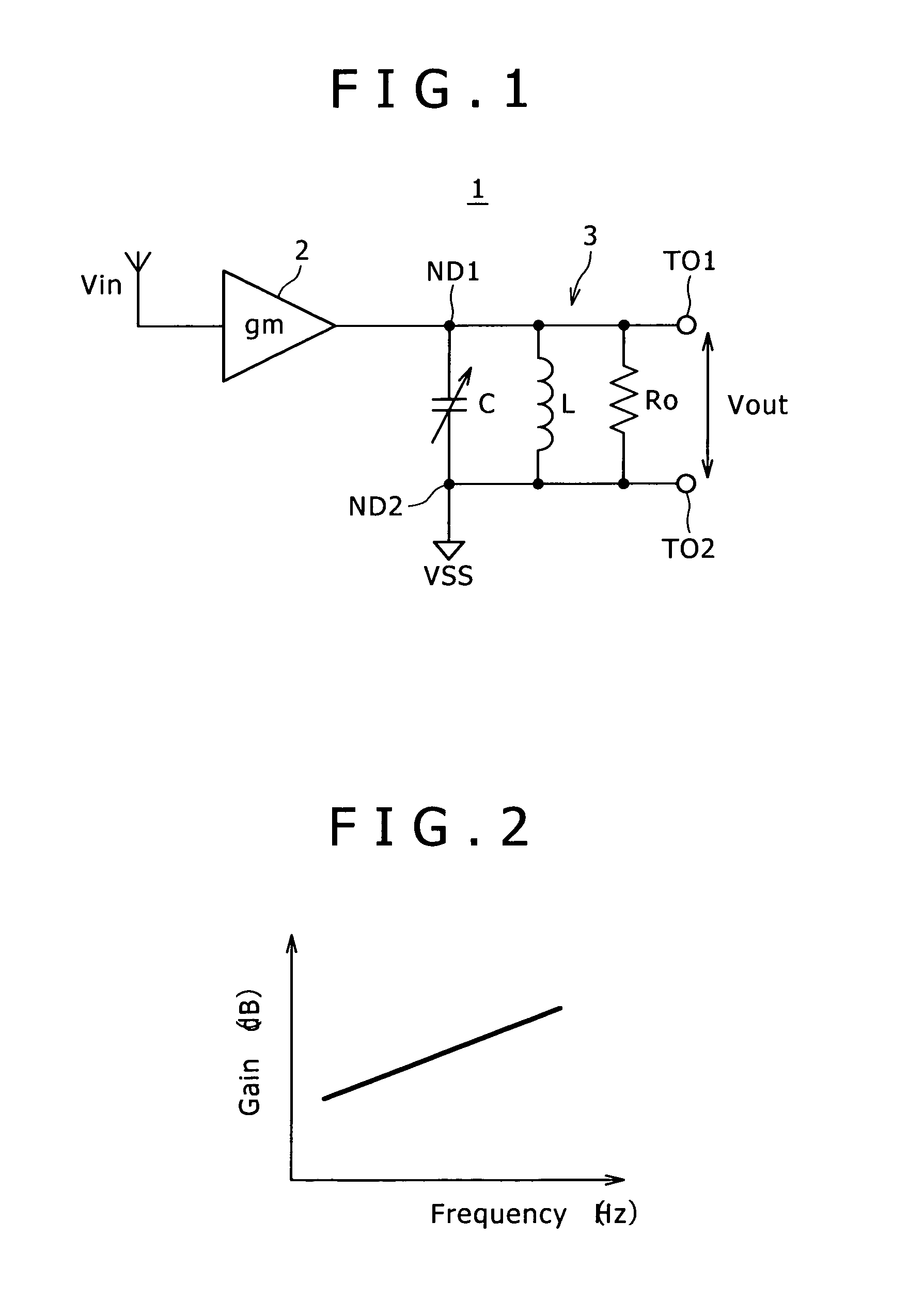
BACKGROUND OF THE INVENTION[0001]1. Field of the Invention[0002]The present invention relates to a high-frequency amplifier applicable to the front-end section of a radio communication apparatus such as a television tuner and also relates to the radio communication apparatus employing the high-frequency amplifier.[0003]2. Description of the Related Art[0004]In most cases, an LC resonator is used as a load borne by a high-frequency amplifier employed in a receiver in which only a desired frequency is selected by imposing band limits on RFs (radio frequencies) of received signals.[0005]FIG. 1 is a circuit diagram showing a typical configuration of a high-frequency amplifier 1 employed in a front-end circuit to serve as an amplifier which includes a parallel LC resonator used as a load circuit 3 borne by a gm amplifier 2 employed in the high-frequency amplifier 1.[0006]That is to say, as shown in the circuit diagram, the high-frequency amplifier 1 employs the gm amplifier 2, the load c...
Claims
Login to View More Application Information
Patent Timeline
 Patent Type & AuthorityPatents(United States)
IPC IPC(8): H04B1/38H03F1/44H03H5/02H04B1/18
CPCH03F2200/378H03F3/189H03F2200/391
InventorTAKAHASHI, KATSUAKISASHO, NOBORUYOSHIKAWA, NAOTOOKANOBU, TAIWA
OwnerSATURN LICENSING LLC