
Livestock feed mixer

a technology for mixing machines and livestock feed, which is applied in the direction of rotary stirring mixers, grain treatment, transportation and packaging, etc., can solve the problems of low supply of high quality forages, reduced milk production, and large differences in the volume and nutrient composition of feed to be given to such a herd

Inactive Publication Date: 2014-02-18
CLOVERDALE EQUIP
View PDF15 Cites 21 Cited by
  • Summary
  • Abstract
  • Description
  • Claims
  • Application Information

AI Technical Summary

Benefits of technology

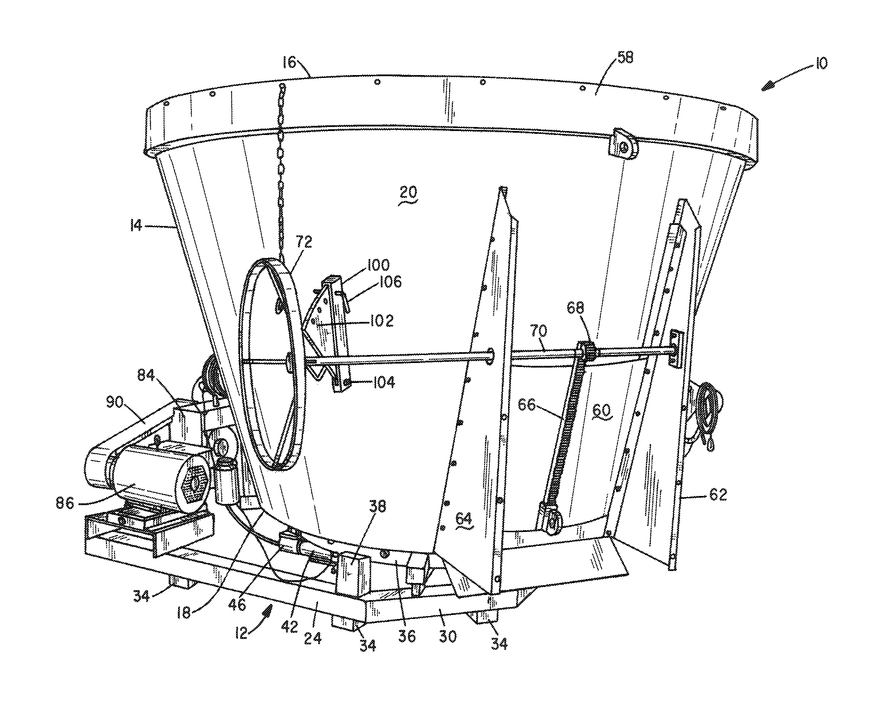
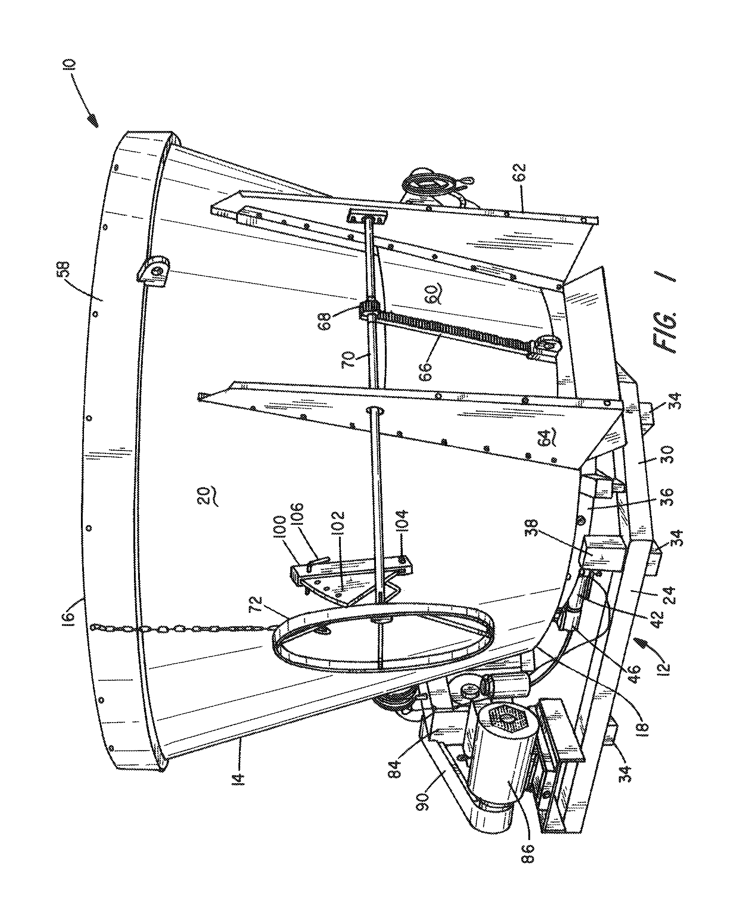
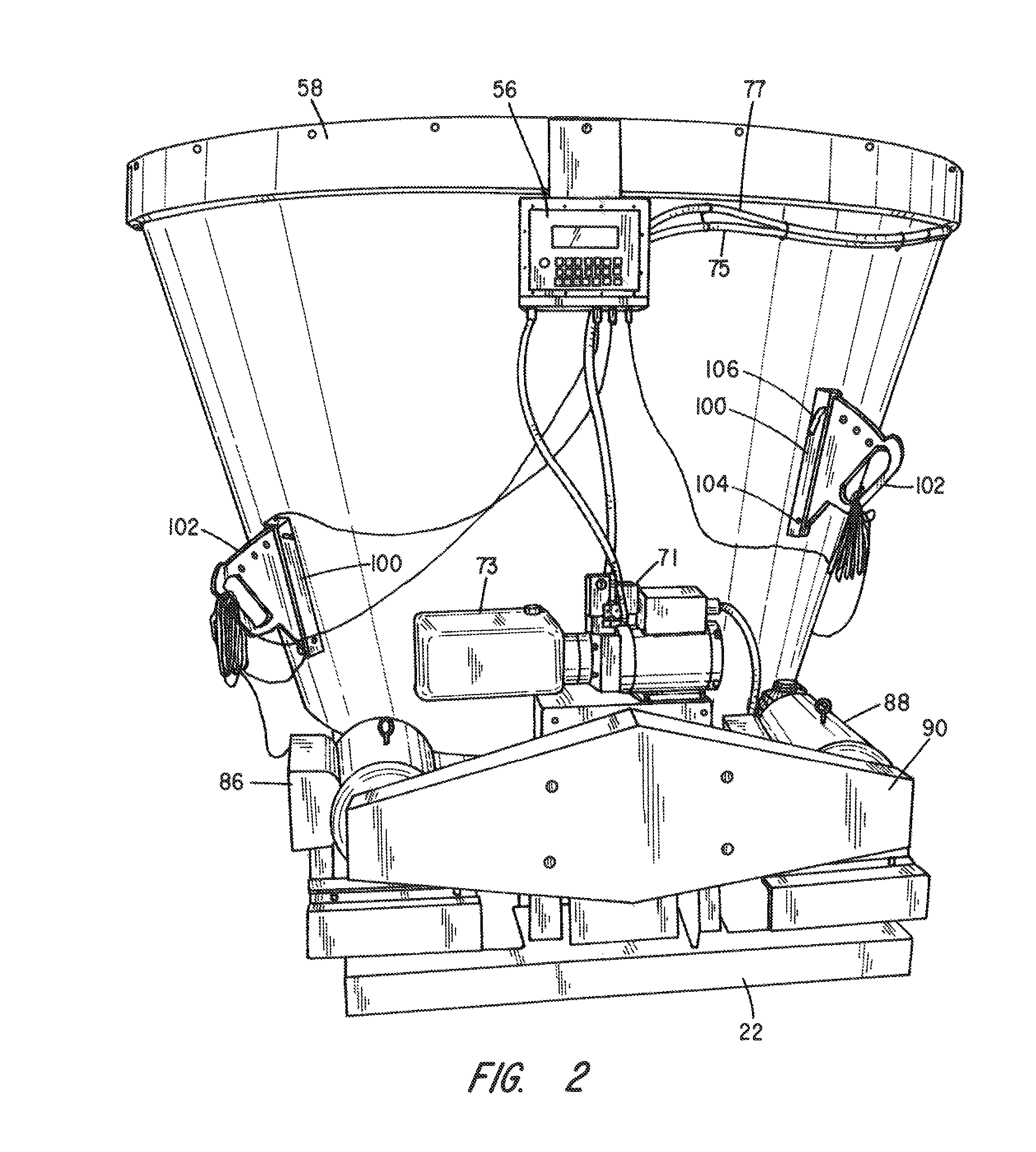
The present invention is a mixer for agricultural animal feed which includes a frustal cone-shaped tub with a closed bottom and an open top. An auger with a vertical shaft and helical fin configuration is supported in the bottom of the tub and is rotated by a motor. The tub has a discharge opening that can be opened and closed by a movable door member. A circular reinforcing band with an L-shaped angle bar is welded onto the tub to provide reinforcement without creating a shelf for collecting and spoiling feed. The auger shaft is driven through a planetary gearbox, which is powered by electric motors. The orientation of the tub's discharge opening can be adjusted to meet different installation requirements.

Problems solved by technology

Distinctly different diets are required for each of these three stages of the lifecycle, resulting in great differences in the volumes and nutrient composition of the feed to be given to such a herd.
However, poor growing, harvesting and / or drying conditions often result in a low supply of high quality forages.
If all low quality forages are fed to dairy cows, decreases in intake often result, and milk production decreases because of insufficient nutrients.
By blending together all the forages, grains, commodities and protein and mineral-vitamin supplements, cows are less able to selectively consume individual ingredients.
However, many horizontal auger mixers do not handle grass hay or baleage well in that these types of feeds tend to wrap around the augers.
A problem exists with stationary mixers of the vertical auger type in that they must be especially designed to accommodate a placement relative to infeed and discharge conveyors commonly used with such mixers.
This presents a problem for the mixer manufacturer in that the location of the discharge door of the mixer tub must conform to a customer's particular layout.
However, such thinner gauge sidewall may need a reinforcing flange surrounding the upper open end of the tub.
A drawback of this approach has been the fact that feed tends to collect on the rim reinforcement structure that over time will rot, become moldy and may later enter a batch of feed being processed.
Another drawback of prior art, vertical auger, feed mixers is that the optimum auger speed for mixing is slower than that required for discharging the already mixed feed through the tub's discharge opening and on to a discharge conveyor leading to the animal's feeding site.

Method used


Image

  • Livestock feed mixer
  • Livestock feed mixer
  • Livestock feed mixer

Examples


Embodiment Construction

[0036]This description of the preferred embodiments is intended to be read in connection with the accompanying drawings, which are to be considered part of the entire written description of this invention. In the description, relative terms such as “lower”, “upper”, “horizontal”, “vertical”, “above”, “below”, “up”, “down”, “top” and “bottom” as well as derivatives thereof (e.g., “horizontally”, “downwardly”, “upwardly”, etc.) should be construed to refer to the orientation as then described or as shown in the drawings under discussion. These relative terms are for convenience of description and do not require that the apparatus be constructed or operated in a particular orientation. Terms such as “connected”, “connecting”, “attached”, “attaching”, “join” and “joining” are used interchangeably and refer to one structure or surface being secured to another structure or surface or integrally fabricated in one piece, unless expressively described otherwise.

[0037]Referring first to FIG. ...


PUM


Abstract

A vertical auger mixer for blending feed ingredients for farm animals has a frusto-conical shaped tub having an open top, a closed bottom and a motor-driven auger journaled for rotation about a vertical axis in the closed bottom. The tub has a discharge opening in a sidewall thereof, the opening having a door movable between an open and closed position. The tub is mounted on a base frame with plural load cells operatively disposed between the base frame and the tub such that the contents of the tub can be weighed and the tub can be rotated to fit installation requirements. An L-shaped tub reinforcing band is welded about the tub surrounding its upper rim in a way that inhibits unwanted collection of feed materials.

Description

BACKGROUND OF THE INVENTION[0001]I. Field of the Invention[0002]This invention relates generally to machinery for processing livestock feed, and more particularly to an improved mixer for blending various ingredients to be fed to dairy herds and other agricultural animals.[0003]II. Discussion of the Prior Art[0004]Dairy operations typically include the milking cowherd with some of the cow population in the non-lactation stage (dry cows) and with growing heifers. Distinctly different diets are required for each of these three stages of the lifecycle, resulting in great differences in the volumes and nutrient composition of the feed to be given to such a herd. In that feed is the major cost associated with dairy production, one way to reduce or control feed costs in dairy farms is to maximize the use of forages in rations. For example, high quality legumes and grasses provide dairy cows and heifers with a good source of protein energy, fiber and minerals. Corn silage is a high energy ...

Claims


Application Information

Patent Timeline
IPC IPC(8): B02C19/22
CPCB01F15/00792A01K5/004B01F7/245B01F7/00616B01F7/24B01F15/00772B01F7/00B01F15/00194B02C19/22B01F27/172B01F27/9212B01F35/2117B01F35/452B01F35/43
Inventor FOX, HARVEY, Z.
Owner CLOVERDALE EQUIP
Learn More