Device and method for configurable transmit and receive antennas

a transmit and receive antenna, configurable technology, applied in the direction of independent non-interaction antenna combinations, wireless communication, wireless commuication services, etc., can solve the problems of large block size, serious performance degradation, and difficulty in achieving the effect of zero loss

Active Publication Date: 2014-02-18
LILEE SYST
View PDF7 Cites 10 Cited by
  • Summary
  • Abstract
  • Description
  • Claims
  • Application Information

AI Technical Summary

Benefits of technology

[0006]A configurable multiple antennas for a time division multiple access (TDMA) radio system between a base station and a locomotive are disclosed. The configurable multiple antennas comprise a first antenna, a second antenna, a first control circuit and a second control circuit. The first antenna is connected to a transmit signal port through a first electrical path, where the first electrical path has substantially zero loss. The second antenna is connected to a receive signal port through a second electrical path, where the second electrical path has substantially zero loss. The first control circuit is coupled between the first antenna and the receive signal port, where a first control signal is operable on the first control circuit to cause the first control circuit in an ON state or an OFF state. When the first control circuit is in the ON state, the first control circuit provides a third electrical path from the first antenna to the receive signal port. The second control circuit is coupled between the second antenna and a ground node, where a second control signal is operable on the second control circuit to cause the second control circuit in the ON state or the OFF state. When the second control circuit is in the ON state, the second antenna is grounded. The configurable multiple antennas can be configured to a selected antenna operation mode according to the first control signal and the second control signal. For example, if the selected antenna operation mode corresponds to a transmit mode, the first control signal and the second control signal can be configured to cause the first control circuit in the OFF state and the second control circuit in the ON state so that a transmit signal is fed from the transmit signal port to the first antenna through the first path and the second antenna is grounded. If the selected antenna operation mode corresponds to a primary received mode, the first control signal and the second control signal can be configured to cause the first control circuit in the OFF state and the second control circuit in the OFF state so that only the second antenna through the second path provides received signals to the receive signal port. If the selected antenna operation mode corresponds to a secondary receive mode, the first control signal and the second control signal can be configured to cause the first control circuit in the ON state and the second control circuit in the OFF state so that the first antenna through the third electrical path and the second antenna through the second electrical path both provide received signals to the receive signal port.
[0007]A method of configuring multiple antennas to a transmit mode, a primary receive mode or a secondary receive mode for a time division multiple access (TDMA) radio system between a base station and a locomotive is disclosed, where the multiple antennas comprises a first antenna connected to a transmit signal port through a first electrical path having substantially zero loss, a second antenna connected to a receive signal port through a second electrical path having substantially zero loss, a first control circuit coupled between the first antenna and the receive signal port, and a second control circuit coupled between the second antenna and a ground node. If the transmit mode is selected, the method applies a first control signal to the first control circuit to cause the first electrical control circuit in an OFF state and applies a second control signal to the second control circuit to cause the second electrical control circuit in an ON state so that a transmit signal is fed from the transmit signal port to the first antenna through the first path and the second antenna is grounded. If the primary receive mode is selected, the method applies the first control signal to the first control circuit to cause the first electrical control circuit in the OFF state and applies the second control signal to the second control circuit to cause the second electrical control circuit in the OFF state so that only the second antenna through the second electrical path provides received signals to the receive signal port. If the secondary receive mode is selected, the method applies the first control signal to the first control circuit to cause the first electrical control circuit in the ON state and applies the second control signal to the second control circuit to cause the second electrical control circuit in the OFF state so that the first antenna through the third electrical path and the second antenna through the second electrical path both provide the received signals to the receive signal port.

Problems solved by technology

It is well known for digital radio systems that there are various channel impairments due to noise, multipath fading and the time-varying channel.
In the PTC system, the weather damage and vandalism are the most frequent reasons that cause the service interruption since the antennas are usually installed outdoors.
Without careful impedance matching for cables, this mechanism usually causes serious performance degradation.
Nevertheless, the technique may require a block size sufficiently large to correct the burst errors and the large block size may not be desirable due to long latency and large memory required to store the block.
However, the use of multiple parallel receivers will increase system cost.

Method used


Image

  • Device and method for configurable transmit and receive antennas
  • Device and method for configurable transmit and receive antennas
  • Device and method for configurable transmit and receive antennas

Examples


Embodiment Construction

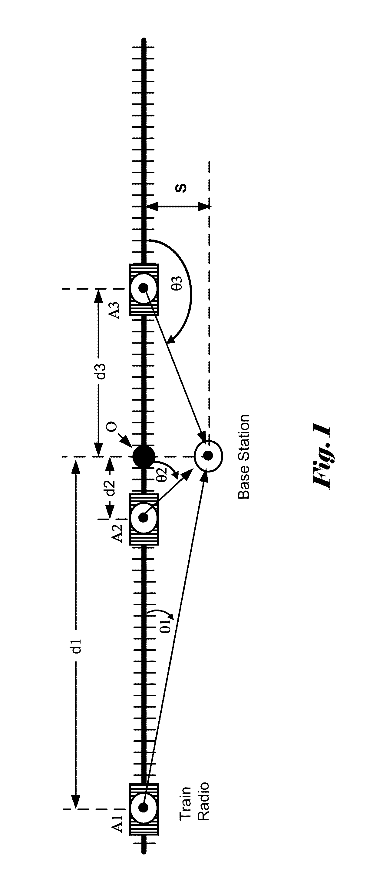
[0011]In the Positive Train Control system, the fast moving train (e.g., The Acela Express by Amtrak travels at 165 MPH at northeast corridor) poses a great challenge to the system design since the channel characteristics change rapidly when the locomotive passes by the wayside base station, also called track-side base station or base station. FIG. 1 illustrates system configuration with a train radio and a track-side radio. The locomotive is travelling at a speed V and is shown at three difference track locations: A1, A2 and A3. The track-side base station is located at a distance S from the track and the track location corresponding to the base station is marked as O in FIG. 1. The distance between the locomotive and the base station is measured between the respective locomotive location and location O. For locations A1, A2 and A3, the respective distances are d1, d2 and d3 as shown in FIG. 1. The respective distances d1, d2 and d3 are referred to as principal distances in this di...


PUM


Abstract

A configurable antenna arrangement is disclosed for wireless Positive Train Control system to overcome the deep fading and fast fading issue. The radio channel between a locomotive on-board radio unit and a base station is subject to fast and deep fading. The channel changes rapidly in a short time comparing to the length of the packet. The invention uses a TX antenna and a RX antenna in a time division multiple access (TDMA) radio system associated with control circuits to provide a configurable antenna sub-system. The antenna sub-system is configurable to provide a TX mode, a primary RX mode and a secondary RX mode. In both the TX mode and the primary RX mode, there is substantially no insertion loss. In the secondary RX mode, the TX antenna is used as the secondary RX antenna to overcome fading caused by Doppler shift.

Description

CROSS REFERENCE TO RELATED APPLICATIONS[0001]The present invention claims priority to U.S. Provisional Patent Application, No. 61 / 408,113, filed Oct. 29, 2010, entitled “Device and Method for Configurable Transmit and Receive Antennas”. The U.S. Provisional Patent Application is hereby incorporated by reference in its entireties.FIELD OF THE INVENTION[0002]The present invention relates to transmit and receive antennas for communication systems. In particular, this invention relates to configurable transmit and receive antennas to reduce the insertion loss for transmit path and / or receive path, to overcome fast fading problem associated with communication between a transmitter and a receiver having fast relative motion, and to improve reliability when either primary antenna is lost due to weather damage or vandalism.BACKGROUND[0003]In a wireless Positive Train Control (PTC) system, a fast-travelling locomotive communicates with a wayside or track-side base station through a radio lin...

Claims


Application Information

Patent Timeline
Patent Type & Authority Patents(United States)
IPC IPC(8): H04W4/00
CPCH01Q1/3216H04B7/00H04W4/00H01Q21/00H01Q21/28H01Q1/00H01Q3/24
Inventor LI, JIA-RULEE, YUEH-JU
Owner LILEE SYST
Why Eureka
Try Eureka