Method for manufacturing heat dissipating apparatus
a technology of heat dissipation apparatus and manufacturing method, which is applied in the direction of manufacturing tools, indirect heat exchangers, lighting and heating apparatus, etc., can solve the problems of permanent damage to humans or the environment, and the generation of heat by electronic components
- Summary
- Abstract
- Description
- Claims
- Application Information
AI Technical Summary
Benefits of technology
Problems solved by technology
Method used
Image
Examples
first embodiment
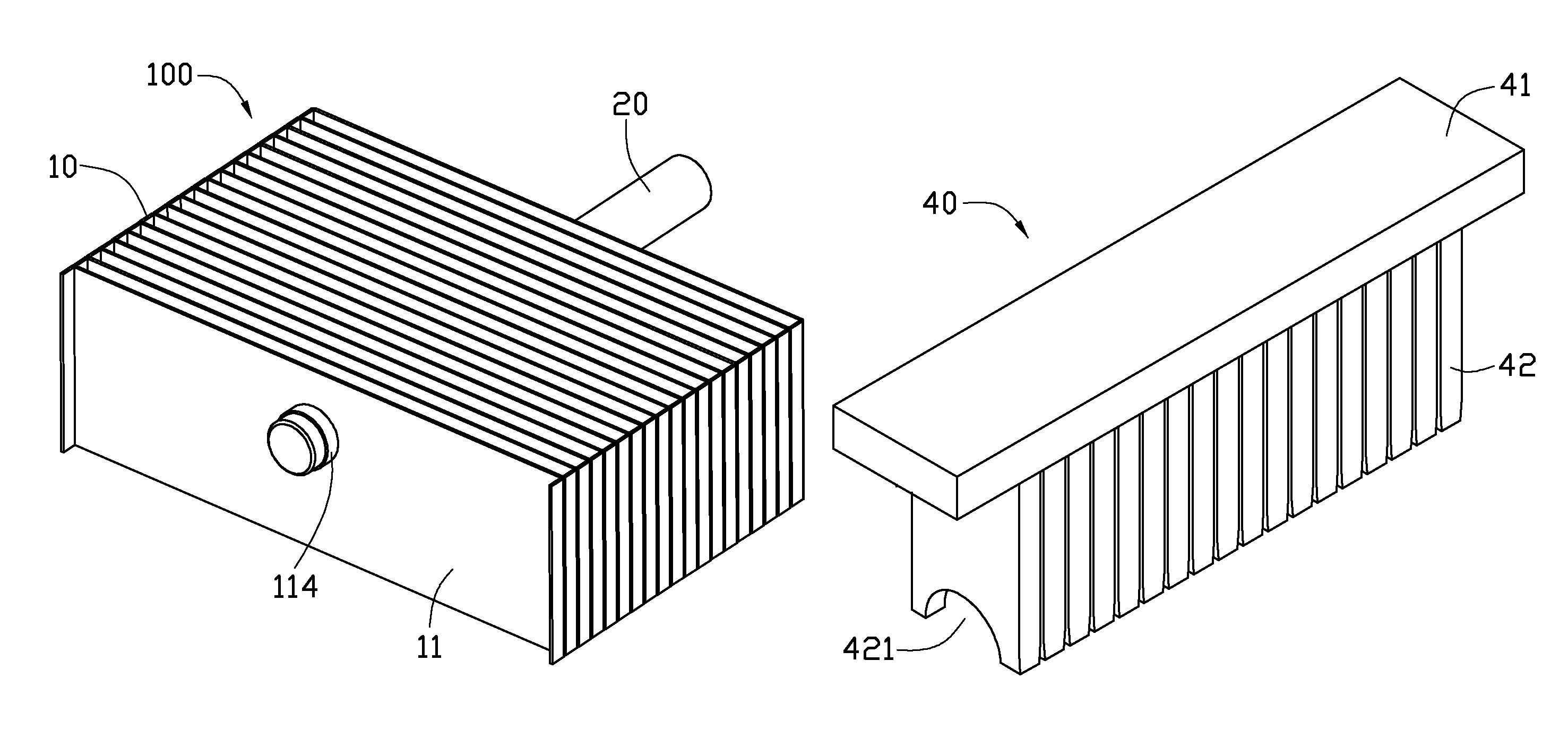
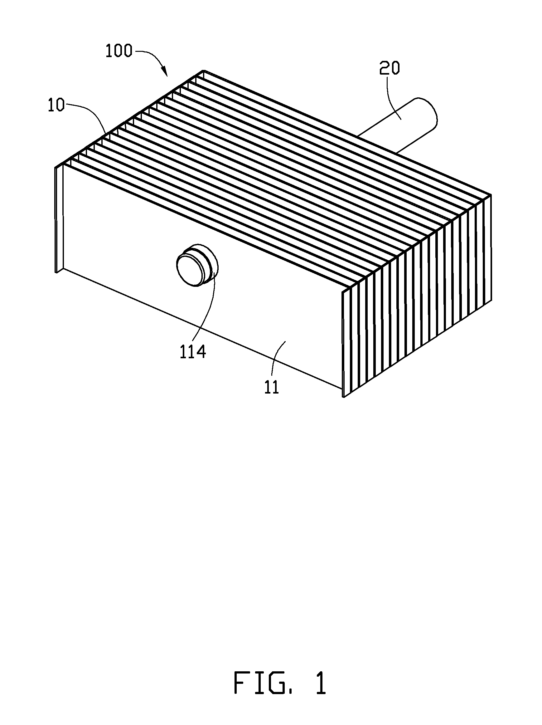
[0012]Referring to FIG. 1, a heat dissipation apparatus 100 manufactured through a manufacturing method in accordance with the present disclosure is shown. The heat dissipation apparatus 100 includes a fin assembly 10, and a heat pipe 20 extending through the fin assembly 10.
[0013]The fin assembly 10 includes a plurality of plate-shaped metallic fins 11 stacked together and spaced apart from each other at constant intervals. An air passage is defined between every two adjacent fins 11. Each of the fins 11 is rectangular and defines a through hole 112 therein, for extending of the heat pipe 20 therethrough. The through holes 112 are circular. An annular collar 114 extends perpendicularly from each fin 11 at an edge of the through hole 112. The heat pipe 20 is interferentially fixed in the collar 114 of each fin 11 (see below).
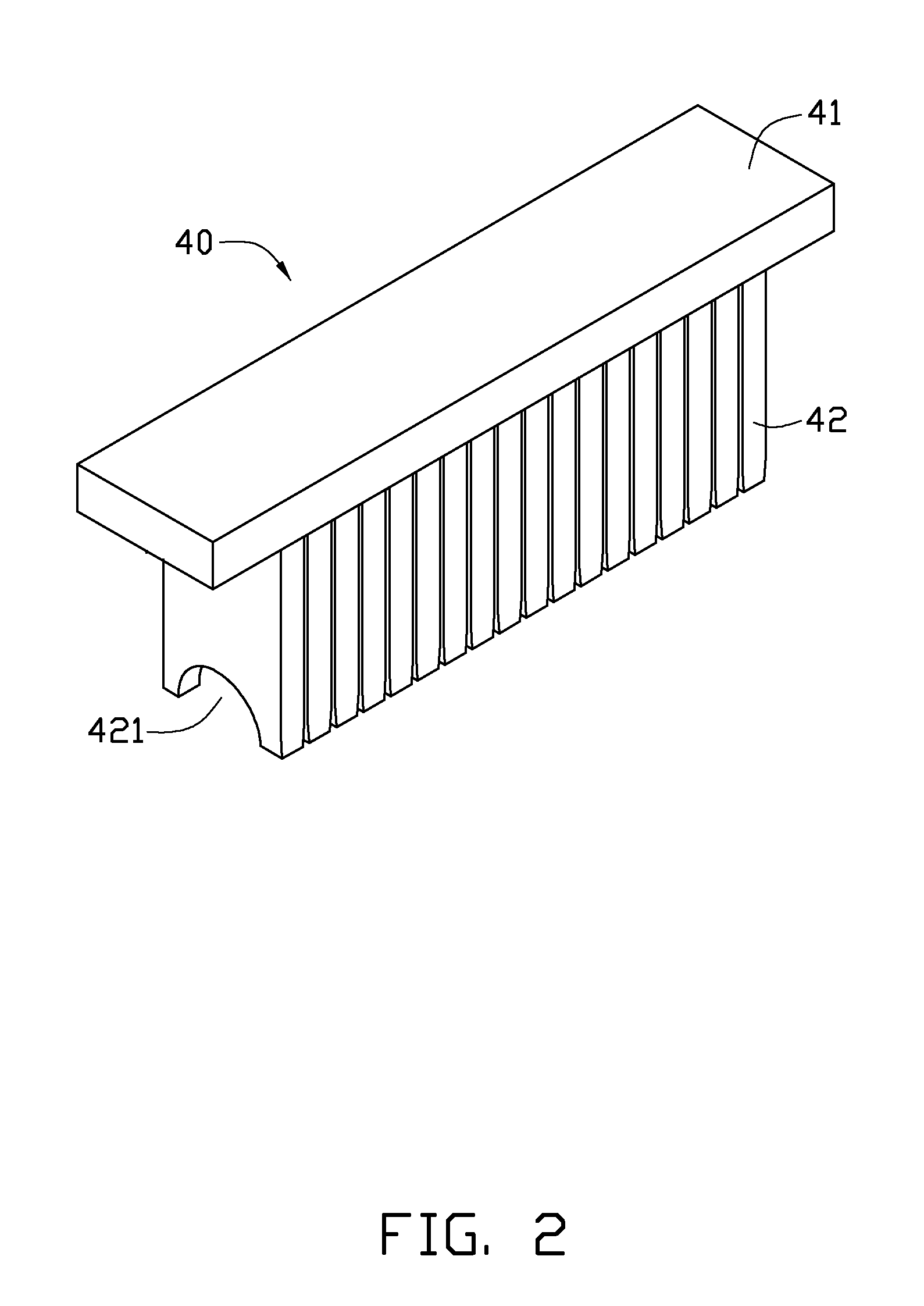
[0014]Referring also to FIGS. 2 and 3, during manufacturing of the heat dissipation apparatus 100, a first punching tool 40, a second punching tool 50 and a pun...
second embodiment
[0021]Referring to FIG. 6, this is a schematic view of a single step of a method for manufacturing the heat dissipation apparatus 100 in accordance with the present disclosure. In this embodiment, the first punching tool 40 is placed above the second punching tool 50, and the fin assembly 10 is prefixed on the second punching tool 50. By this arrangement, each fin 11 of the fin assembly 10 is located between every two adjacent two punching units 52 of the second punching tool 50, and the collar 114 of each fin 11 is held in a recess 521 of a corresponding punching unit 52 of the second punching tool 50. The first punching tool 40 is driven by a punch (not shown) to punch the fin assembly 10 fixed on the second punching tool 50, similar to the procedure shown in FIG. 4 and FIG. 5.
third embodiment
[0022]Referring to FIG. 7, this is a front view of part of a heat dissipation apparatus 100a before a punching process of a method for manufacturing the heat dissipation apparatus 100a in accordance with the present disclosure. In this embodiment, a collar 114a of each fin 11a of the heat dissipation apparatus 100a defines two slots 1141 therein. Each of the slots 1141 is strip-shaped, and extends parallel to an axis of the collar 114a. The two slots 1141 of the collar 114a face each other to divide the collar 114a into two equal parts. This allows the collar 114a to shrink more easily during the punching process. When the punching process is completed, the two slots 1141 of the collar 114a are substantially closed due to the shrinkage of the collar 114a. In this embodiment, the collar 114a defines two slots 1141. Understandably, in other embodiments, one slot 1141 or more than two slots 1141 can be defined in the collar 114a.
PUM
| Property | Measurement | Unit |
|---|---|---|
| outer diameter | aaaaa | aaaaa |
| diameter | aaaaa | aaaaa |
| inner diameter | aaaaa | aaaaa |
Abstract
Description
Claims
Application Information
 - R&D
- Intellectual Property
- Life Sciences
- Materials
- Tech Scout
- Unparalleled Data Quality
- Higher Quality Content
- 60% Fewer Hallucinations
Browse by: Latest US Patents, China's latest patents, Technical Efficacy Thesaurus, Application Domain, Technology Topic, Popular Technical Reports.
© 2025 PatSnap. All rights reserved.Legal|Privacy policy|Modern Slavery Act Transparency Statement|Sitemap|About US| Contact US: help@patsnap.com


