Protective circuit board cover

a protective circuit board and cover technology, applied in the direction of circuit security details, printing, semiconductor/solid-state device details, etc., can solve the problems of ever more complex and intricate interplay, more difficult to unlock and reverse engineer a protected information storage or information processing system, etc., to achieve easy stripping for coating replacement or maintenance/repair, and high frangible

Active Publication Date: 2014-02-25
LOCKHEED MARTIN CORP
View PDF54 Cites 97 Cited by
  • Summary
  • Abstract
  • Description
  • Claims
  • Application Information

AI Technical Summary

Benefits of technology

This patent is about a new method for protecting circuit components from tampering and damage. The method involves applying a protective hardcoat layer on top of an elastomeric undercoat. The elastomeric undercoat acts as an adhesive and helps reduce stress on the circuit components. The hardcoat layer can be applied without needing a photomask and can be easily removed for maintenance or upgrade purposes. The hardcoat layer is designed to destroy embedded components when damaged and can be used as a latent security solution. The elastomeric undercoat can be easily strippable and can contain multiple layers of inter-connected components. Overall, this method provides a cost-effective and efficient way to protect circuit components from tampering and damage.

Problems solved by technology

AT techniques and reverse engineering techniques constantly develop in response to each other in an ever more complex and intricate interplay of security measures and counter-measures.
Another area of interest related to anti-tamper techniques is masking or otherwise obscuring the actual component content, wiring or trace structure and layout of a circuit board, and / or intellectual property associated with the fabrication of an integrated circuit, thereby making it more difficult to unlock and reverse engineer a protected information storage or information processing system.

Method used


Image

  • Protective circuit board cover
  • Protective circuit board cover
  • Protective circuit board cover

Examples


Embodiment Construction

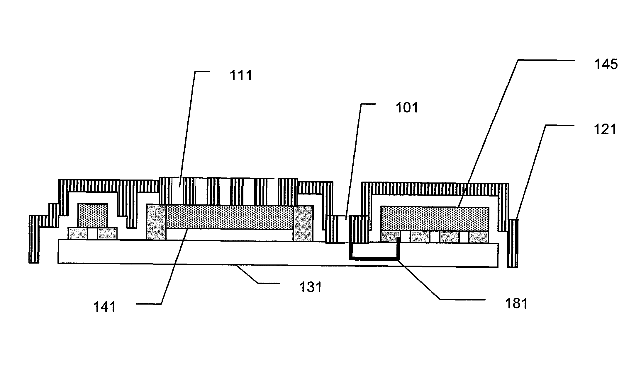
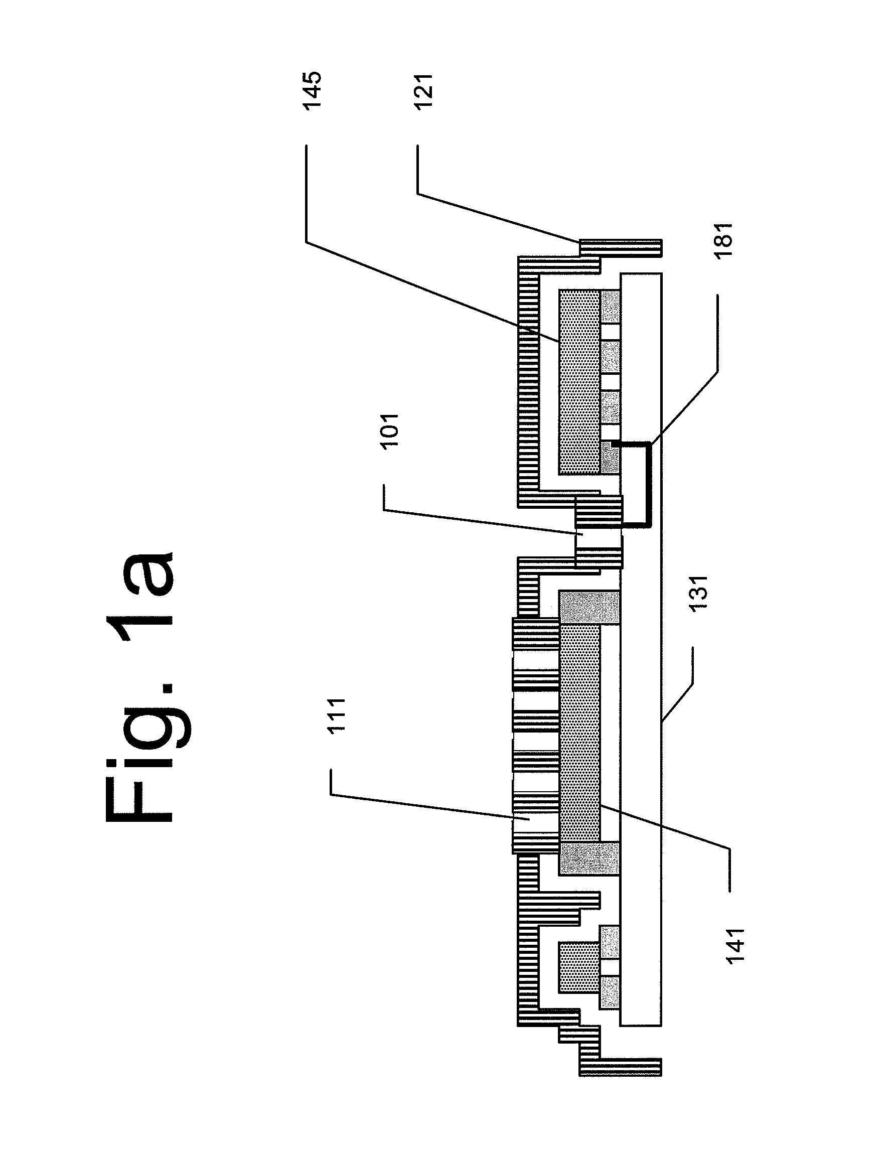
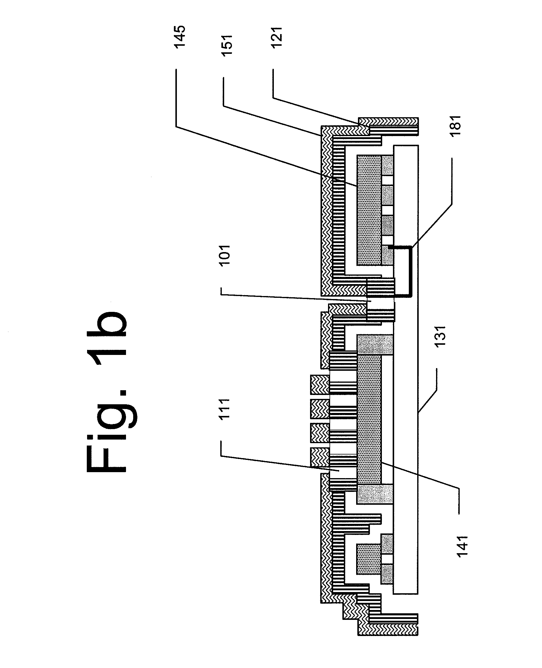
[0057]The following detailed description of the invention refers to the accompanying drawings. The same reference numbers in different drawings identify the same or similar elements. Also, the following detailed description does not limit the invention. Instead, the scope of the invention is defined by the appended claims and equivalents thereof.

[0058]Anti-tamper techniques and reverse-engineering prevention solutions are a mainstay of securing and preventing unauthorized use and duplication of technologies. This is especially relevant for makers of customized, specialized or otherwise sensitive electronic, electro-optical, or electro-mechanical devices where physical properties and / or specific component designs play key roles in the effective operation of the device. Devices such as transponders having unique frequency responses based on the size, shape, configurable parameters, and / or composition of internal antennas / resonators, circuits performing various forms of data encoding, ...


PUM

PropertyMeasurementUnit
areaaaaaaaaaaa
dielectricaaaaaaaaaa
dielectric propertiesaaaaaaaaaa

Abstract

A protective, anti-tamper coating and methods of coating creation and application are provided. The coating may include an elastomeric layer to allow for strippability / removal. The coating may also include a “smart layer” for tamper detection, imaging prevention, and tamper prevention or underlying device de-activation / alteration upon tamper detection. The coating may also include one or more ground planes around the smart layer and one or more frangible layers designed to interrupt or alter smart layer function in the event of a tamper attempt.

Description

[0001]The present invention claims benefit of priority to Provisional Application 61 / 251,565, filed in the U.S. Patent and Trademark Office on Oct. 14, 2009, the entire contents of which are hereby incorporated by reference. The present invention also claims benefit of priority to Provisional Application 61 / 348,156, filed in the U.S. Patent and Trademark Office on May 25, 2010, the entire contents of which are hereby incorporated by reference.TECHNICAL FIELD OF THE INVENTION[0002]The present invention relates in general to anti-tamper solutions to prevent unauthorized access to and modification of components or information stored in electromagnetic (EM) domains (electronic, magnetic, or optical modules), components of a printed circuit or wiring board, or in integrated circuits, optical, magnetic, or other EM devices.BACKGROUND OF THE INVENTION[0003]Anti-tamper (AT) devices and techniques have long been used to protect and secure proprietary and secret products and information from ...

Claims


Application Information

Patent Timeline
Patent Type & Authority Patents(United States)
IPC IPC(8): H05K1/16H01L23/00
CPCH01L2924/3011H01L2924/09701H01L23/57H01L23/573H01L2924/0002H05K1/0275H05K3/284H01L23/576G06F21/73Y10T29/49227H01L2924/00
Inventor ADAMS, CHRISTIANKELLEY, MATTHEWNELSON, PATRICK
Owner LOCKHEED MARTIN CORP
Why Eureka
Try Eureka