Locomotion of amorphous surface robots

a robot and amorphous technology, applied in the field of locomotion of amorphous robots, can solve the problems of conventional propulsion devices being fouled and stuck, and the design of conventional rovers being less than optimal in these applications, so as to improve surface mobility, enhance protection from the elements, and improve surface mobility

Inactive Publication Date: 2014-03-04
NASA
View PDF5 Cites 3 Cited by
  • Summary
  • Abstract
  • Description
  • Claims
  • Application Information

AI Technical Summary

Benefits of technology

[0006]An amorphous surface robot is disclosed herein. In its various embodiments, the amorphous robot provides improved surface mobility. As used herein, the term “amorphous robot” refers to a robot lacking a rigidly defined and unchanging shape. The presently disclosed robots change shape in the direction of intended travel to provide improved surface mobility along with enhanced protection from the elements.
[0007]The presently disclosed amorphous robot designs rely on one or more of the following principles: (1) the circulation of fluid in the desired direction of travel via a fully enclosed valve assembly; (2) the sequential switching of polarity of one or more fully enclosed electromagnets; and / or (3) the sequential expansion and deflation of an active material-based polymeric sac or cell. All disclosed robot designs enable movement with respect to a solid surface, as opposed to movement through free space or a liquid operating environment, without the use of wheels, tracks, or legs. All designs are fully scalable, and thus can be readily adapted as needed to the particular application and operating environment in which the robots are to be used.

Problems solved by technology

Robots are used in a host of applications, many of which present unique design challenges.
In particularly sandy or loamy soil environments such as the lunar or Martian surfaces, conventional propulsion devices may become fouled and stuck.
Conventional rover designs may be less than optimal in these applications due to certain design limitations that may cause the rovers to become irretrievably stuck in the rubble or other difficult to navigate surface features.

Method used


Image

  • Locomotion of amorphous surface robots
  • Locomotion of amorphous surface robots
  • Locomotion of amorphous surface robots

Examples


Embodiment Construction

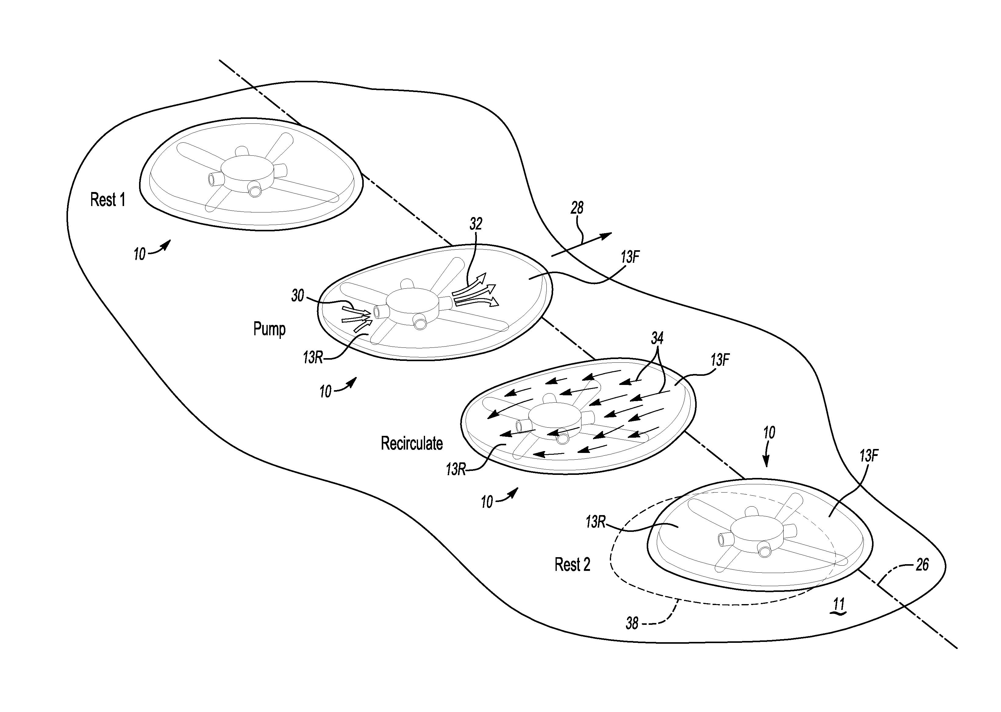
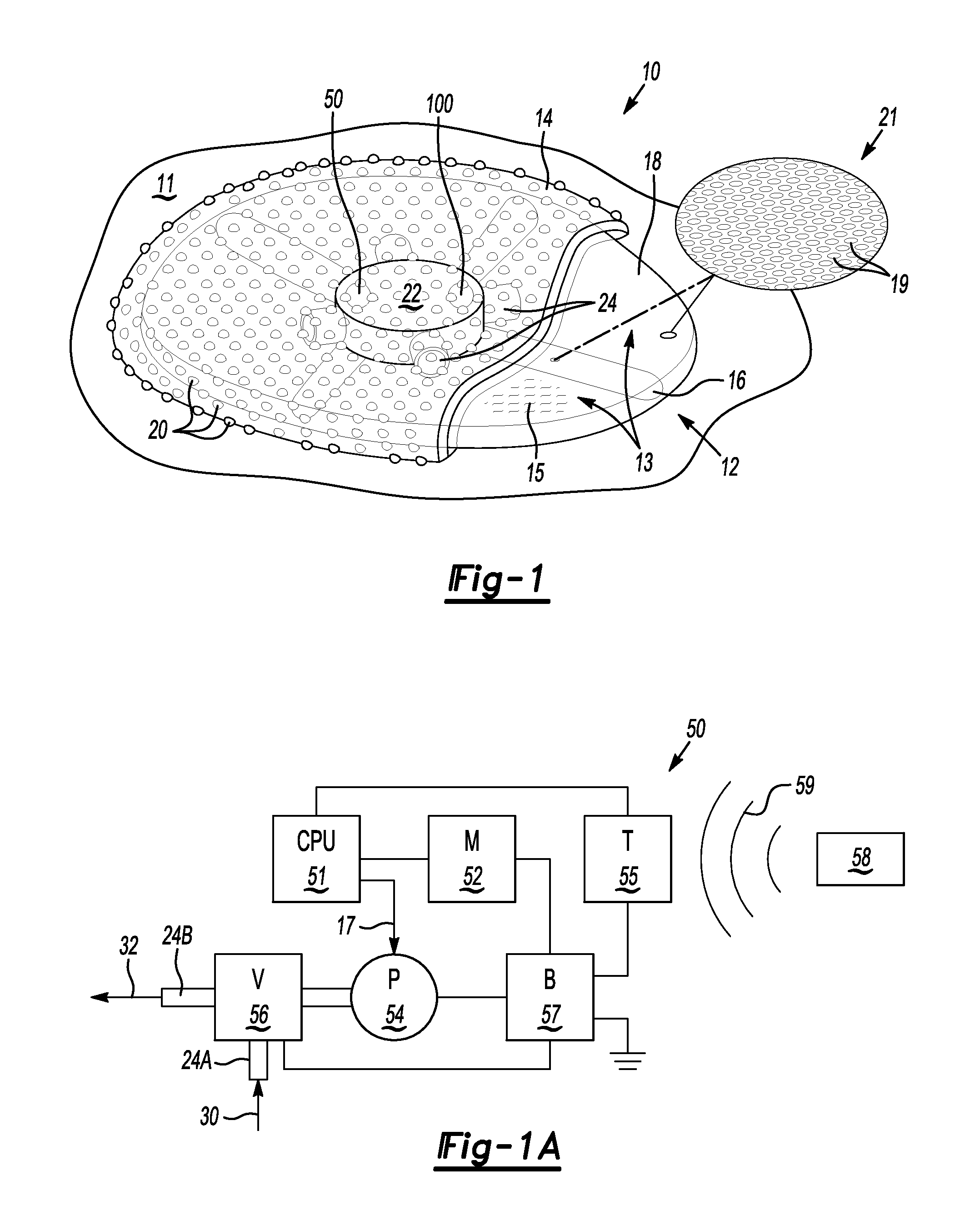
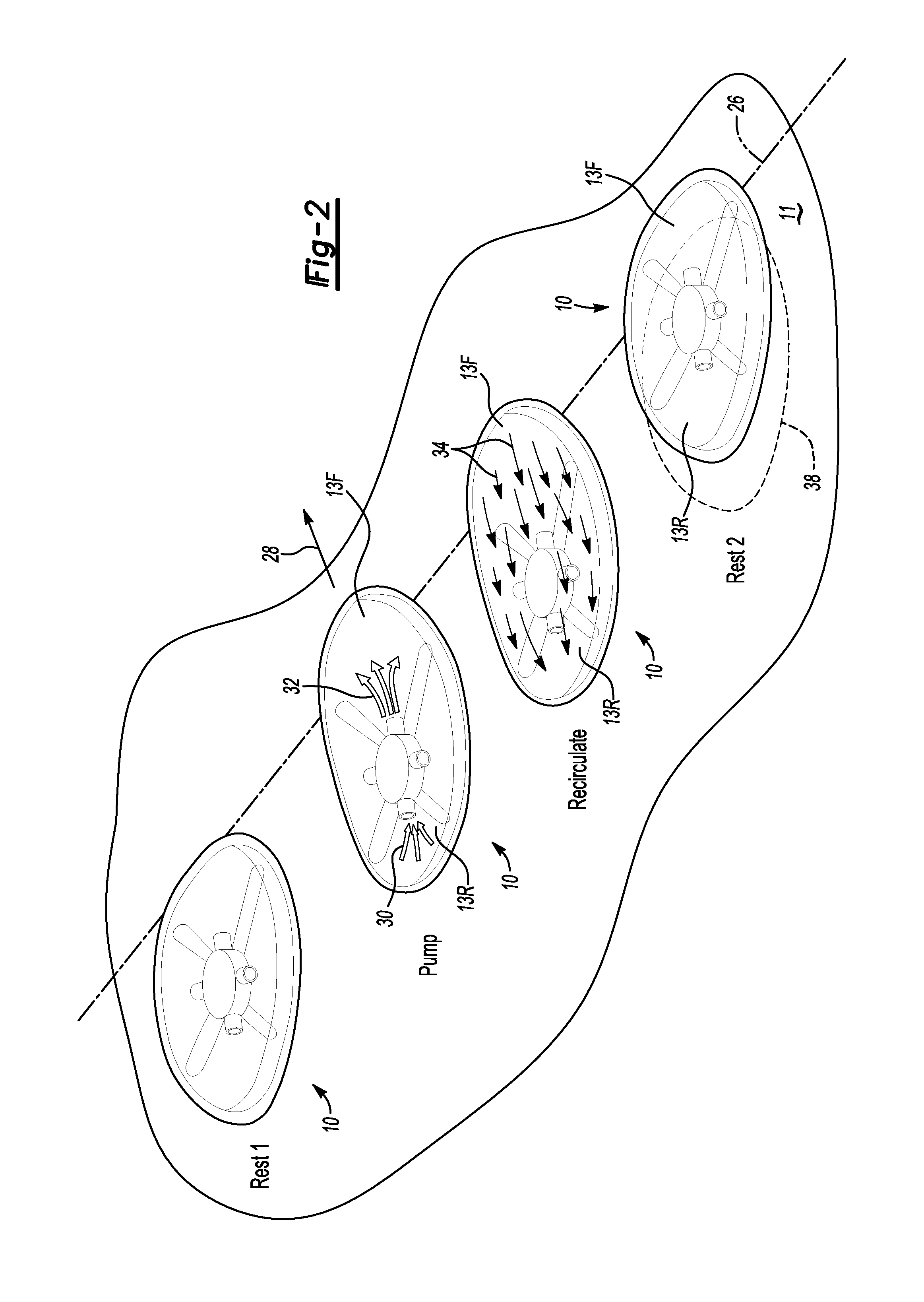
[0030]Referring to the drawings, wherein like reference numbers correspond to like or similar components throughout the several figures, an amorphous robot 10 is shown in FIG. 1. The robot 10 is positioned with respect to a surface 11, for instance a terrestrial surface or a lunar, Martian, or other extraterrestrial surface. The robot 10 includes a valve assembly 22 and a bladder 12, the latter defining a plurality of compartments 13. An outer layer 14 fully encapsulates the bladder 12 such that the bladder 12 is completely shielded and thus isolated from dirt or debris of the surface 11 and the surrounding atmosphere. A portion of the outer layer 14 is removed in FIG. 1 to more clearly illustrate the structure of the bladder 12 encapsulated by the outer layer 14.

[0031]The outer layer 14 may include surface asperities 20 which form pseudopodia (false feet). Asperities 20 may be, by way of example, surface features such as nodules, fingers, or bumps. The asperities 20 extend from the...


PUM


Abstract

An amorphous robot includes a compartmented bladder containing fluid, a valve assembly, and an outer layer encapsulating the bladder and valve assembly. The valve assembly draws fluid from a compartment(s) and discharges the drawn fluid into a designated compartment to displace the designated compartment with respect to the surface. Another embodiment includes elements each having a variable property, an outer layer that encapsulates the elements, and a control unit. The control unit energizes a designated element to change its variable property, thereby moving the designated element. The elements may be electromagnetic spheres with a variable polarity or shape memory polymers with changing shape and / or size. Yet another embodiment includes an elongated flexible tube filled with ferrofluid, a moveable electromagnet, an actuator, and a control unit. The control unit energizes the electromagnet and moves the electromagnet via the actuator to magnetize the ferrofluid and lengthen the flexible tube.

Description

CROSS-REFERENCE TO RELATED APPLICATIONS[0001]This application claims the benefit of U.S. Provisional Patent Application No. 61 / 431,168 filed on Jan. 10, 2011, which is hereby incorporated by reference in its entirety.STATEMENT REGARDING FEDERALLY SPONSORED RESEARCH OR DEVELOPMENT[0002]The invention described herein was made by an employee of the United States Government, and may be manufactured and used by or for the Government for Government purposes without the payment of any royalties thereon or therefore.TECHNICAL FIELD[0003]The present disclosure relates to the locomotion of amorphous robots.BACKGROUND OF THE INVENTION[0004]Robots are electromechanical devices that perform work tasks automatically or autonomously. Robots are used in a host of applications, many of which present unique design challenges. For instance, complex surface-roving robots generally referred to as “rovers” may be used in space exploration missions as well as in Earth-based search and rescue operations. C...

Claims


Application Information

Patent Timeline
Patent Type & Authority Patents(United States)
IPC IPC(8): B25J11/00
CPCG05D1/021B64G1/16B62D57/021B62D57/00Y10S901/01B62D57/02
Inventor BRADLEY, ARTHUR T.
Owner NASA
Why Eureka
Try Eureka