Automated beverage brewing method

a technology of automatic brewing and hot beverage, which is applied in beverage vessels, household appliances, kitchen equipment, etc., can solve the problems of dangerous and unsanitary spillage of hot beverage on floors, counter tops, and operator's skin or clothing, and achieve the effect of convenient upward movement of the piston

Active Publication Date: 2014-03-04
FOOD EQUIP TECH
View PDF10 Cites 21 Cited by
  • Summary
  • Abstract
  • Description
  • Claims
  • Application Information

AI Technical Summary

Benefits of technology

[0028]Preferably, the pressure sensitive valve is a ball valve with a movable ball that is automatically moved to a closed position by a bias spring when the pressure on the valve is less than the preselected minimum opening pressure. After the valve is closed at the end of the seeping period, the brew chamber may be removed without residual beverage in the brew chamber leaking or dripping out of the brew chamber. Preferably, the pressure is controlled by movement of a piston having an air-tight seal with the interior surface of the bre

Problems solved by technology

Disadvantageously, the extraction is uneven and difficult to control, with most of the extraction occurring during the beginning of the brew cycle
Another disadvantage is that commencement of a new brew cycle is delayed while waiting for the end of the drip period.
It is necessary to wait because failure to do so results in dangerous and unsanitary spillage of hot beverage on floors, counter tops and onto the operator's skin or clothing.
However, suffer from an open drain brew chamber, and another disadvantage of such espresso machines is that they are generally suitable for making only a single small cup of espresso per brew cycle.
Another problem with known press-type brewers is caused by the plunger coming into direct, physical, intimate contact with the beverage and the wet beverage ingredient.
In the event that different types of coffee or different flavored coffee are being successively brewed, then there can be flavor contamination from one batch to the next due to residual beverage and wet, spent beverage ingredient adhered to the plunger and associated parts

Method used


Image

  • Automated beverage brewing method
  • Automated beverage brewing method
  • Automated beverage brewing method

Examples


Embodiment Construction

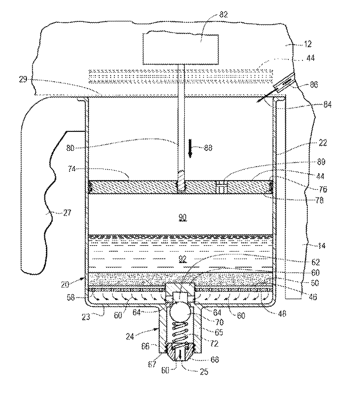
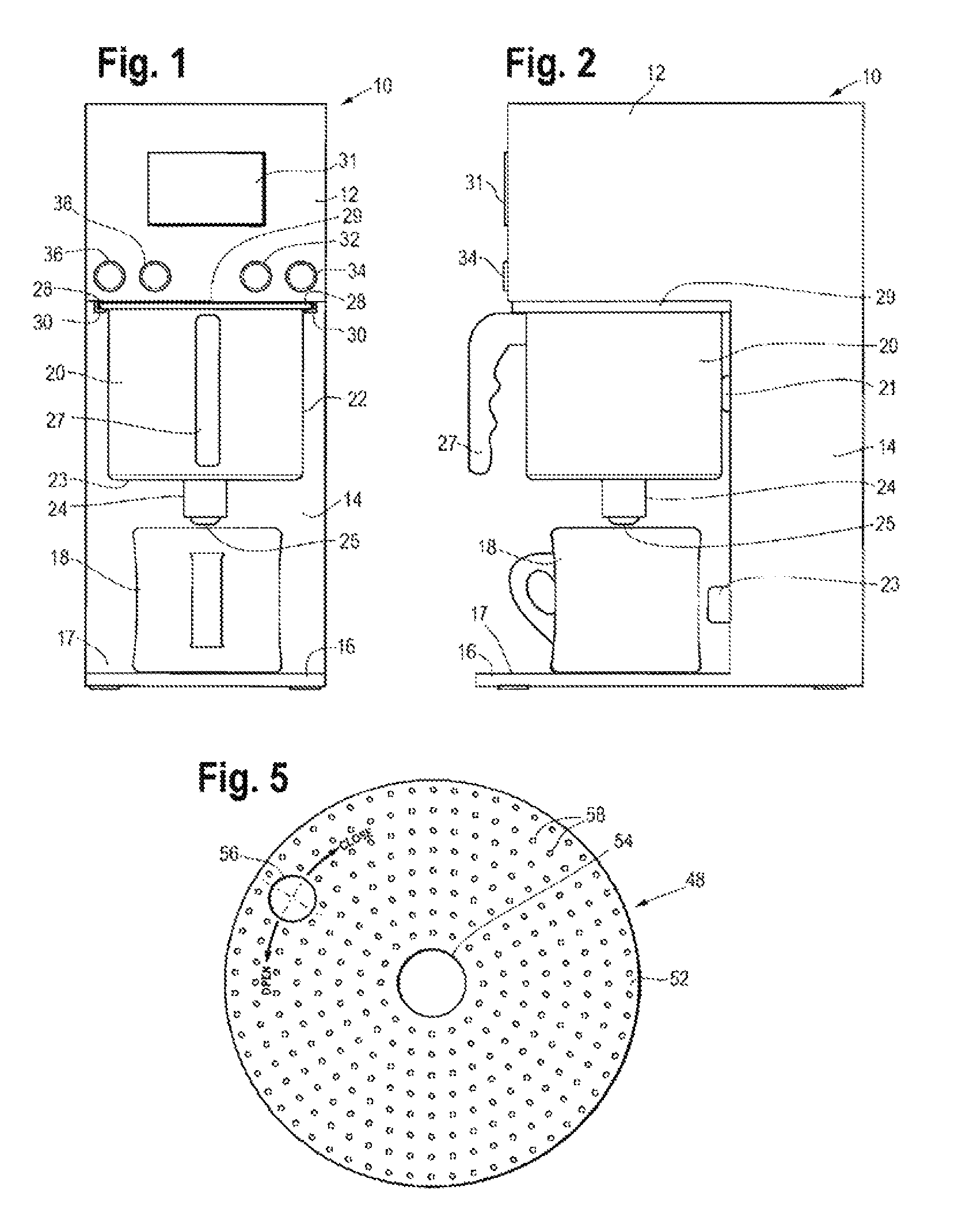
[0035]Referring to FIGS. 1 and 2, a preferred embodiment of the hot beverage brewer 10 of the present invention is seen to include an upper housing section 12 supported in cantilever fashion by an aft housing section 14. The aft housing section 14, in turn, is supported by a forwardly extending foot member 16 that extends beneath a forward section of the upper housing section 12.

[0036]The forwardly extending foot member 16 may include a removable drip tray (not shown), but due to the drip prevention aspects of the invention, such a drip tray may not be needed. In any event, with or without a drip tray, a support surface 17 provides underlying support of a beverage container 18.

[0037]The brewer 10 is scalable upwards from one having capacity to make only a single serving of beverage for each brew cycle to one that is capable of making four liters of beverage or more per brew cycle. In the case of the brewer 10 being configured to make only a single serving of beverage per brew cycle,...


PUM


Abstract

An electrical, automatic hot beverage brewer (10) and method of brewing in which a removable brew chamber (20) has a drain hole (25) in the bottom fitted with a normally closed, pressure responsive brew chamber drain valve assembly (24) maintained in a normally closed position except when pressure against the drain valve (24) exceeds a preselected minimum pressure limit that is greater than the fluidic pressure applied by virtue of head pressure of a full load of hot water and a piston (74) is moved within the brew chamber to control the opening and closing of the drain valve (24) When the piston (74) moves downwardly toward the drain hole the air pressure of a pocket of air (90) above the beverage (92) in the brew chamber (20) is increased to open at the end of a seeping period when it is desired to rapidly expel freshly brewed beverage out the brew drain valve at a relatively rapid rate depending upon the total of the hydraulic pressure and the added pressure from the air pressure source to avoid the need to wait for the end of a drip period. The drain valve (24) automatically closes after the piston (74) is removed from the brew chamber (20) to enable removal of the brew chamber (20) from a brewer housing (12) without risks of hot beverage leaking out of the brew chamber (20).

Description

CROSS-REFERENCE TO RELATED APPLICATION[0001]This application claims the benefit under 35 USC 119(e) of U.S. provisional patent application 61 / 310,119, filed Mar. 3, 2010, which is hereby incorporated by reference.BACKGROUND OF THE INVENTION[0002]1. Field of the Invention[0003]This invention generally relates to hot beverage brewers, such a coffee or tea brewers, and more particularly, to an electrical hot beverage brewer[0004]2. Discussion of the Prior Art[0005]Electrical coffee or tea brewers or the like of the type that hold the beverage ingredient in a brew chamber for a preselected seeping time period and then quickly discharge the freshly brewed beverage out of the brew chamber are known.[0006]Drip-type beverage brewers operate by filling a brew chamber with hot water that immediately begins to percolate through a layer of beverage ingredient and out of an open drain hole as soon as the first water is added until all the beverage has passed through the ingredient. The rate at w...

Claims


Application Information

Patent Timeline
IPC IPC(8): A47J31/32
CPCA47J31/0663A47J31/0631A47J31/02A47J31/10A47J31/32
Inventor BANASIK, GREGORY
Owner FOOD EQUIP TECH
Why Eureka
Try Eureka