Methods, systems, and computer readable media for mapping regions in a model of an object comprising an anatomical structure from one image data set to images used in a diagnostic or therapeutic intervention

Active Publication Date: 2014-03-04
THE UNIV OF NORTH CAROLINA AT CHAPEL HILL
View PDF8 Cites 26 Cited by
  • Summary
  • Abstract
  • Description
  • Claims
  • Application Information

AI Technical Summary

Benefits of technology

[0022]As used herein, the term “m-rep” refers to a medial atom representation of an object or of object image data. An m-rep is an explicit mathematical representation (i.e., a model) of an object's geometry in Riemannian space that represents a geometric object as a set of connected continuous medial manifolds. For 3D objects these medial manifolds may be formed by the centers of all spheres that are interior to the object and tangent to the object's boundary at two or more points. The medial description is defined by the centers of the inscribed spheres and by the associated vectors, called spokes, from the sphere centers to the two respective tangent points on the object boundary. It is appreciated that in addition to representing the surface boundaries of objects, m-reps may also represent object interiors in terms of

Problems solved by technology

While TRUS reveals the overall shape of the prostate well, a major disadvantage is the inability to differentiate between normal and cancerous tissues inside the prostate.
Due to this limitation, tissue samples are collected based on a pre-defined grid pattern applied to all patients.
Unfortunately the false negative rate of this approach is high (˜25-30%).
Moreover, even when a biopsy is positive, the tumor may be sampled incompletely, leading to an erroneously low Gleason score (tumor grade), and perhaps to inappropriate treatment decisions.
These undesired outcomes significantly affect the patient's quality of life and contribute to health care burden and costs.
TRUS-guided biopsies suffer problems of not allowing doctors accurately enough to preferentially take biopsy samples from tissues ins

Method used


Image

  • Methods, systems, and computer readable media for mapping regions in a model of an object comprising an anatomical structure from one image data set to images used in a diagnostic or therapeutic intervention
  • Methods, systems, and computer readable media for mapping regions in a model of an object comprising an anatomical structure from one image data set to images used in a diagnostic or therapeutic intervention
  • Methods, systems, and computer readable media for mapping regions in a model of an object comprising an anatomical structure from one image data set to images used in a diagnostic or therapeutic intervention

Examples


Example

Exemplary Operating Environment

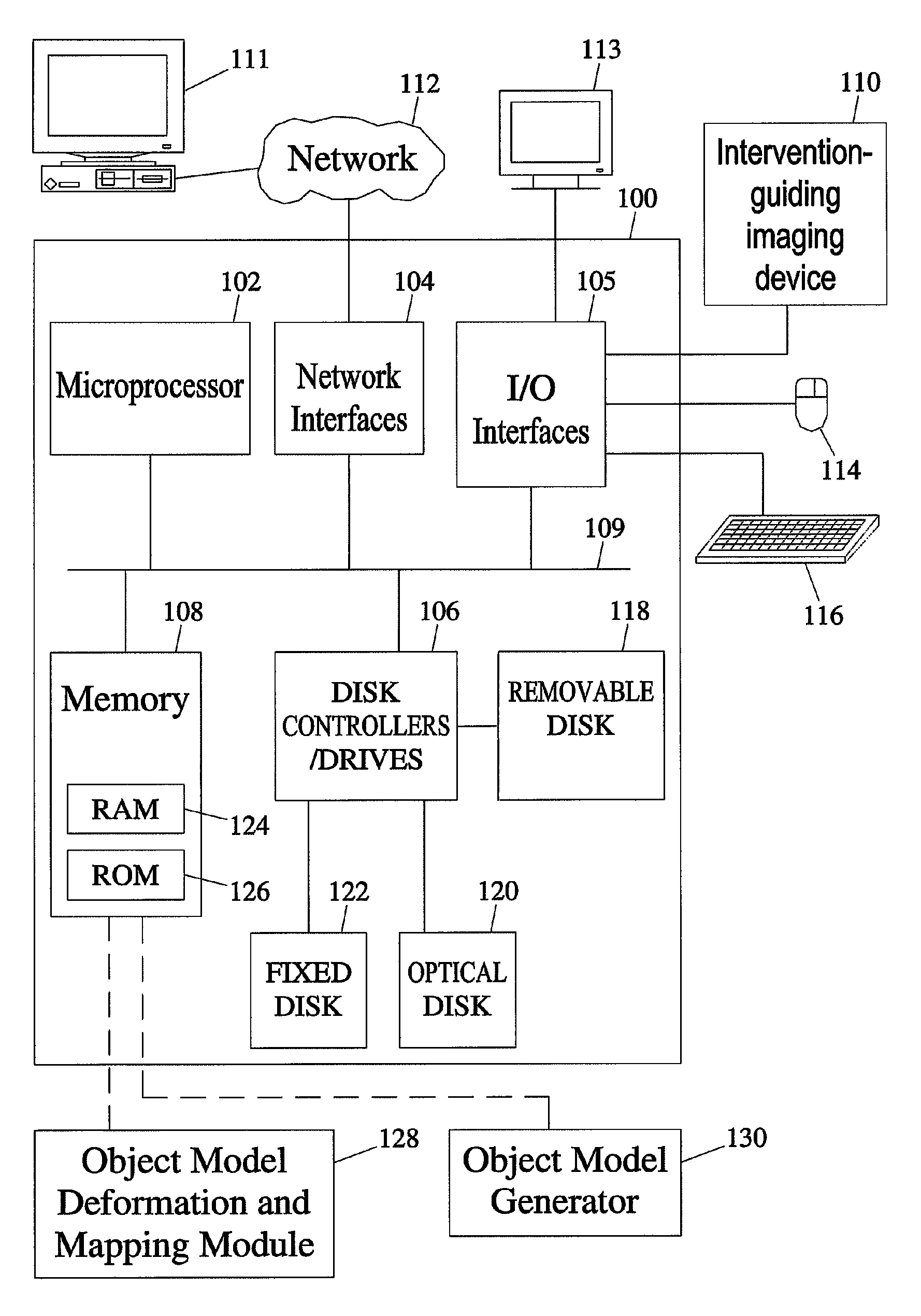
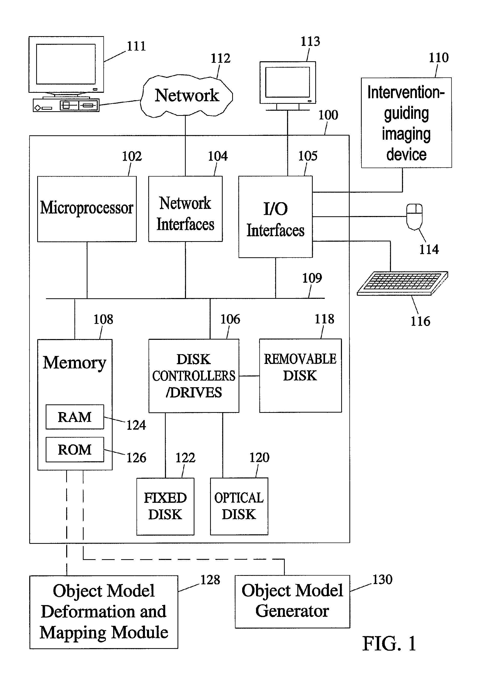
[0048]The subject matter described herein includes methods and systems for mapping an object comprising an anatomical structure in a planning image and an intervention target region derived from an image registered with the planning image to intervention-guiding image data showing the object. The methods and systems of the subject matter described herein can be implemented in hardware, firmware, software, or any combination thereof. In one exemplary embodiment, the methods and systems that perform object modeling for mapping an object model comprising an anatomical structure in a planning image to an intervention-guiding image data may be implemented as application software adapted to execute on a general purpose computer. FIG. 1 illustrates an exemplary operating environment for the methods and systems for mapping the object model comprising the anatomical structure in the planning image to the intervention-guiding image data according to an embodimen...


PUM


Abstract

Methods, systems, and computer readable media for mapping a model of an object comprising an anatomical structure in a planning image and an intervention target region within it to intervention-guiding image data are disclosed. According to one method, an initial medial representation object model (m-rep) of an object comprising an anatomical structure is created based on image data of at least a first instance of the object. A patient-specific m-rep is created by deforming the initial m-rep based on planning image data of at least a second instance of the object, wherein the at least second instance of the object is associated with the patient. An intervention target region within the m-rep is identified in an image registered with the planning image. The patient-specific m-rep is correlated to the intervention-guiding image data of the at least second instance of the object, deformed from the planning image. The intervention target region is transferred to the intervention-guiding image according to the transformation between the m-rep in the planning image and the m-rep in the intervention-guiding image.

Description

RELATED APPLICATIONS[0001]This application claims the benefit of U.S. Provisional Patent Application Ser. No. 60 / 999,420 filed Oct. 18, 2007 and U.S. Provisional Patent Application Ser. No. 61 / 087,026 filed Aug. 7, 2008; the disclosures of which are incorporated herein by reference in their entireties.GRANT STATEMENT[0002]Some of the work involved in creating this invention was supported by NCI and NIBIB Grant Number P01 EB002779. Thus, the U.S. Government has certain rights to this invention.TECHNICAL FIELD[0003]The subject matter described herein relates to medical image segmentation and analysis. More specifically, the subject matter relates to methods, systems, and computer readable media for mapping regions in a model of an object comprising an anatomical structure from one image data set to images used in a diagnostic or therapeutic intervention.BACKGROUND[0004]Prostate cancer (CaP) is a major health issue in the United States, with 240,000 diagnoses and 30,000 deaths in 2005....

Claims


Application Information

Patent Timeline
IPC IPC(8): A61B5/103G06K9/00
CPCG06T2207/10132G06T7/0083G06K2209/051G06T2207/20128G06T7/0012G06T2207/20044G06T2207/10072G06T2207/30081A61B2019/505G06T7/0089G06T2207/20124G06T7/0032G06K9/621A61B2034/105G06T7/344G06T7/12G06T7/149G06V10/7557G06V2201/031
Inventor CHANEY, EDWARD L.PIZER, STEPHENKWOCK, LESTERWALLEN, ERICHYSLOP, WILLIAMBROADHURST, ROBERT
Owner THE UNIV OF NORTH CAROLINA AT CHAPEL HILL
Why Eureka
Try Eureka