
Bicycle motor control apparatus

a motor control and bicycle technology, applied in the direction of vehicle position/course/altitude control, process and machine control, instruments, etc., can solve the problems of inconvenient control for the rider, inappropriate gear change operation, and inability to obtain assisting for

Active Publication Date: 2014-03-04
SHIMANO INC
View PDF9 Cites 4 Cited by
  • Summary
  • Abstract
  • Description
  • Claims
  • Application Information

AI Technical Summary

Benefits of technology

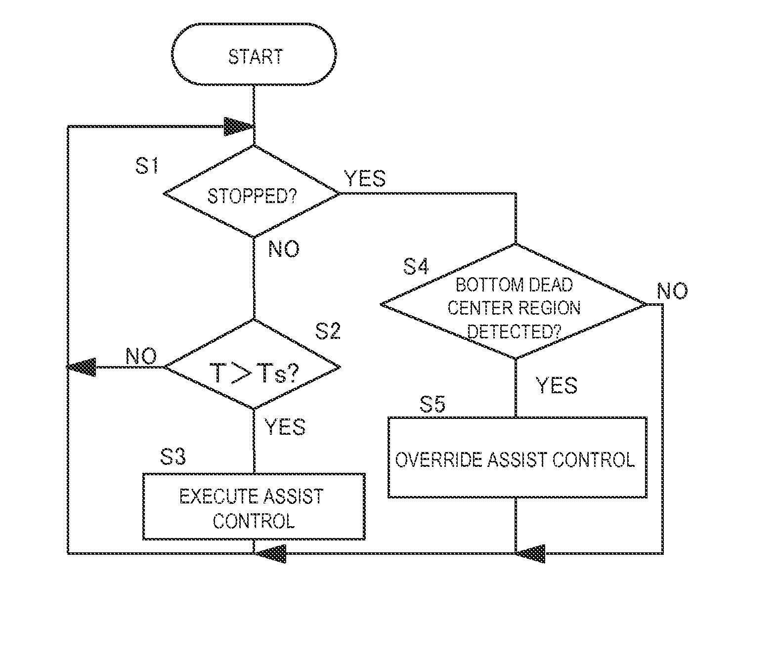
[0011]With this bicycle motor control apparatus, driving of the motor is prohibited when it is determined that the bicycle or the bicycle crank is stopped and the bicycle crank position is in a prescribed region including a bottom dead center position. Thus, while the bicycle crank is positioned within the prescribed region, the motor will not be driven even if a rider uses a particular mounting technique in which the rider places one foot on a pedal and kicks the ground with the other foot when starting the bicycle into motion. As a result, in a bicycle in which the motor supplements a drive provided by the rider, it is possible to suppress an occurrence of an undesired supplemental force increase that accompanies a pedaling force increase occurring due to the prescribed mounting technique. Also, when the bicycle is started into motion by sitting on the saddle and turning the bicycle crank, control can be executed to deliver an appropriate assisting force once the bicycle crank exits the prescribed region and the amount of time elapsed after the bicycle starts moving is irrelevant. Furthermore, the occurrence of situations in which an assisting force is not delivered even though the bicycle crank position is such that an assisting force from the motor is necessary can be suppressed. Meanwhile, in a bicycle in which the motor drives an external transmission, an inappropriate gear change operation does not occur even if the bicycle crank turns while the bicycle crank is within the prescribed region. As a result, a motor can be controlled appropriately in accordance with a riding technique used when starting the bicycle into motion.
[0013]Thus, it is possible to detect if the bicycle crank is within the prescribed region based on a magnetic force in a non-contact manner without being affected by dirt or other contaminants. As a result, the bicycle crank position can be detected with good accuracy even if the bicycle crank position detecting device is installed on a bicycle that is ridden outdoors where it can easily become dirty. Also, the bicycle crank position can be detected with a simple mechanism.
[0014]A bicycle motor control apparatus according to a third aspect is the bicycle motor control apparatus according to the second aspect, wherein the bicycle crank position determining section determines if the bicycle crank is in the prescribed region based on outputs from the magnetic force detecting elements. With this aspect, a determination as to whether or not the bicycle crank position is within the prescribed region can be accomplished easily using a combination of outputs from two magnetic force detecting elements arranged corresponding to the prescribed region. Specifically, some people perform the particular mounting technique starting from the left side of the bicycle (viewed from the rear) and others perform the technique from the right side. Thus, there are two bottom dead center positions 180 degrees apart from each other, i.e., one for the left crank and one for the right crank. However, using a combination of outputs from two magnetic force detecting elements, a determination can easily be accomplished with respect to a prescribed region including two bottom dead center positions that are 180 degrees apart.
[0019]With this aspect, the motor is not driven when the bicycle crank is positioned within the prescribed region, even if a rider performs the particular mounting technique. As a result, when the motor supplements a drive provided by the rider, it is possible to suppress an occurrence of an unexpected speed increase caused by a pedaling force increase. Also, when the bicycle is started into motion by sitting on the saddle and turning the bicycle crank, control can be executed to deliver an appropriate assisting force once the bicycle crank exits the prescribed region regardless of the amount of time elapsed since the bicycle started moving. As a result, a motor can be controlled appropriately in accordance with a riding technique used when starting the bicycle into motion and the occurrence of situations in which an assisting force is not delivered even though the bicycle crank position is such that an assisting force from the motor is necessary can be suppressed.
[0020]A bicycle motor control apparatus according to a seventh aspect is a bicycle motor control apparatus according to any one of the first to fifth aspects, wherein the motor is a motor that drives an external transmission. With this aspect, in a bicycle in which the motor drives an external transmission, an inappropriate gear change operation will not occur even if the bicycle crank turns while the bicycle crank is within the prescribed region. As a result, a motor for driving an external transmission can be controlled appropriately in accordance with a riding technique used when starting the bicycle into motion.
[0022]Driving a motor is prohibited when a crank position is determined to be in a prescribed region including bottom dead center. Thus, while the bicycle crank is positioned within the prescribed region, the motor will not be driven even if a rider uses a particular mounting technique in which the rider places one foot on a pedal and kicks the ground with the other foot. As a result, an assisting motor can be controlled appropriately in accordance with a riding technique used when starting the bicycle into motion.

Problems solved by technology

Thus, the conventional technology detects if the bicycle crank is rotating and executes a gear change control such that the motor does not operate when the bicycle crank is not rotating.
Thus, even if for example, a rider starts the bicycle into motion while sitting on the saddle, an assisting force cannot be obtained until the prescribed amount of time has elapsed.
Consequently, when, for example, a rider starts the bicycle into motion on an uphill slope while seated on the saddle, the control is inconvenient to the rider because an assisting force cannot be obtained for a prescribed amount of time.
With the technology presented in Japanese Laid-Open Patent Publication No. 2006-008062, since the gear change control can be executed when the bicycle crank rotates, there is a possibility that a slight rotation of the bicycle crank occurring when a rider starts the bicycle into motion using the particular mounting technique will cause an inappropriate gear change operation to occur while the bicycle is in a state in which changing gears cannot actually be accomplished.
Thus, while the bicycle crank is positioned within the prescribed region, the motor will not be driven even if a rider uses a particular mounting technique in which the rider places one foot on a pedal and kicks the ground with the other foot when starting the bicycle into motion.
Thus, while the bicycle crank is positioned within the prescribed region, the motor will not be driven even if a rider uses a particular mounting technique in which the rider places one foot on a pedal and kicks the ground with the other foot.

Method used


Image

  • Bicycle motor control apparatus
  • Bicycle motor control apparatus
  • Bicycle motor control apparatus

Examples


first embodiment

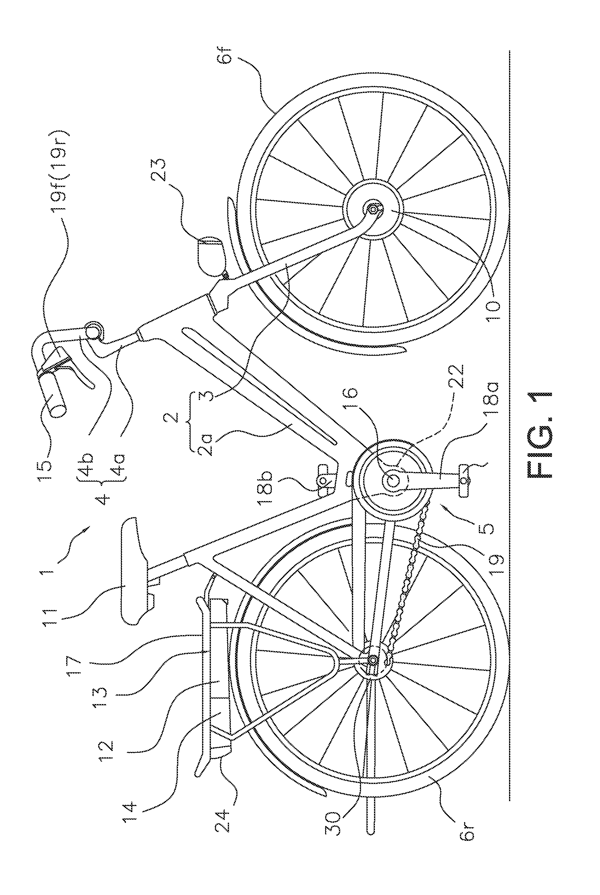
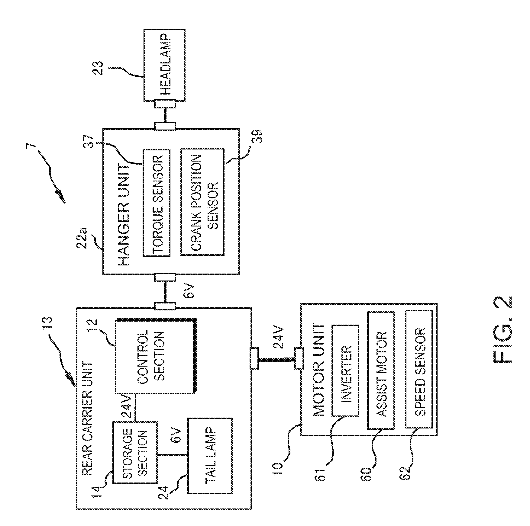
[0032]Referring initially to FIG. 1, a bicycle 1 is illustrated with a bicycle motor control apparatus in accordance with a The bicycle is an electric powered bicycle configured to assist a rider by using a motor unit 10 to supplement a drive force (e.g., a pedaling force) imparted by the rider. The bicycle 1 includes a frame 2 having a frame body 2a and a front fork 3. As shown in FIG. 1, the front fork 3 is attached to a frontward portion of the frame body 2a such that it can pivot about a slanted axis. The bicycle 1 further includes a handlebar unit 4 attached to the upper end of the front fork 3 for steering the bicycle 1. The bicycle 1 further includes a drive train 5, a front wheel 6f, a rear wheel 6r, an electrical system 7 (see FIG. 2), a saddle 11, a headlamp 23 and a tail lamp 24. The drive train 5 includes a crank axle 16, a right crank 18a, a left crank 18b, a chain 19 and an internally geared hub 30. The bicycle 1 includes other conventional components such as a front ...

second embodiment

[0061]With the second embodiment, inappropriate gear change operations will not occur even if the right crank or the left crank is turned or rocked while inside the prescribed region α. As a result, the front gear changing motor 140f and the rear gear changing motor 140r of the external transmissions can be controlled appropriately in accordance with a riding technique used when starting the bicycle into motion.

[0062]Although embodiments of the present invention have been presented heretofore, the present invention is not limited to these embodiments and various modifications can be made without departing from the scope of the invention as defined by the claims.

[0063]Although in the previously explained embodiment the bicycle crank position sensor has a magnet and magnetic force detecting elements, the bicycle motor control apparatus is not limited to using such a crank position sensor. It is acceptable for the bicycle crank position sensor to be, for example, a sensor that can dete...


PUM


Abstract

A bicycle motor control apparatus includes a bicycle crank position detecting device, a bicycle crank position determining section, a stop determining section and a motor control section. The bicycle crank position detecting device detects a position of a bicycle crank. The bicycle crank position determining section determines if the bicycle crank is in a prescribed region including a bottom dead center position based on a detection result from the bicycle crank position detecting device. The stop determining section that determines a stopped state indicative of at least one a bicycle crank stopped state and a bicycle stopped state. The motor control section selectively outputs a motor driving command and stops the output of the motor driving command during a period in which the bicycle crank position determining section determines that the bicycle crank is in the prescribed region and the stop determining section determines that the stopped state exists.

Description

CROSS-REFERENCE TO RELATED APPLICATIONS[0001]This application claims priority under 35 U.S.C. §119 to Japanese Patent Application No. 2011-163880, filed Jul. 27, 2011. The entire disclosure of Japanese Patent Application No. 2011-163880 is hereby incorporated herein by reference.BACKGROUND[0002]1. Field of the Invention[0003]This invention generally relates to a motor control apparatus. More specifically, the present invention relates to a bicycle motor control apparatus that controls a motor installed on a bicycle. The invention also relates to a bicycle equipped with the motor control apparatus.[0004]2. Background Information[0005]In an electric powered bicycle that supplements a drive provided by the rider using a motor, a pedaling force is detected and the motor is controlled to deliver a supplemental drive force in accordance with the pedaling force. Among bicycle riding techniques, there is a particular bicycle mounting technique called the “cowboy mount” or “side mount” in wh...

Claims


Application Information

Patent Timeline
Patent Type & Authority Patents(United States)
IPC IPC(8): B60L9/00B62M6/45
CPCB62M6/45B62M6/50
Inventor SUZUKI, TOSHIKUNIUMEZAWA, YOSHIOSASAKI, BUNGO
Owner SHIMANO INC
Learn More