Coupler for a quick change insert rotary cutting tool

a technology of insert rotary cutting tools and couplers, which is applied in the direction of tool workpiece connection, shaping cutters, manufacturing tools, etc., can solve the problems of wasting expensive shank materials, less economical, and complicating the manufacturing process of couplers

Active Publication Date: 2014-03-11
KENNAMETAL INC
View PDF30 Cites 15 Cited by
  • Summary
  • Abstract
  • Description
  • Claims
  • Application Information

AI Technical Summary

Problems solved by technology

However the increasing global pricing of modern tool alloys along with recently developed intricate surface treatment make it less economical, as the expensive shank material is wasted.
The need to provide such an undercut complicates the manufacturing process of the coupler, such action being particularly awkward when the coupler is closed around its periphery since access from the front end is restricted.

Method used


Image

  • Coupler for a quick change insert rotary cutting tool
  • Coupler for a quick change insert rotary cutting tool
  • Coupler for a quick change insert rotary cutting tool

Examples


Embodiment Construction

[0032]In the following description of some embodiments, identical components that appear in more than one figure or that share similar functionality will be referenced by identical reference symbols.

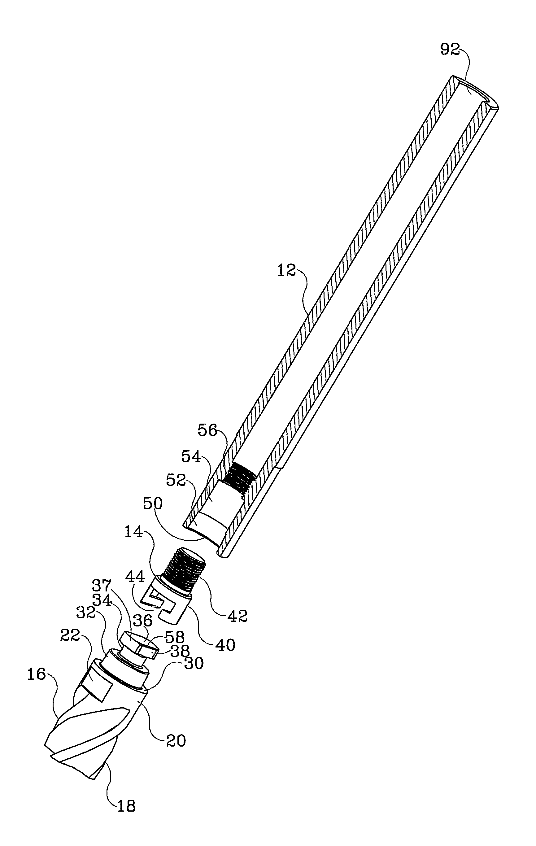
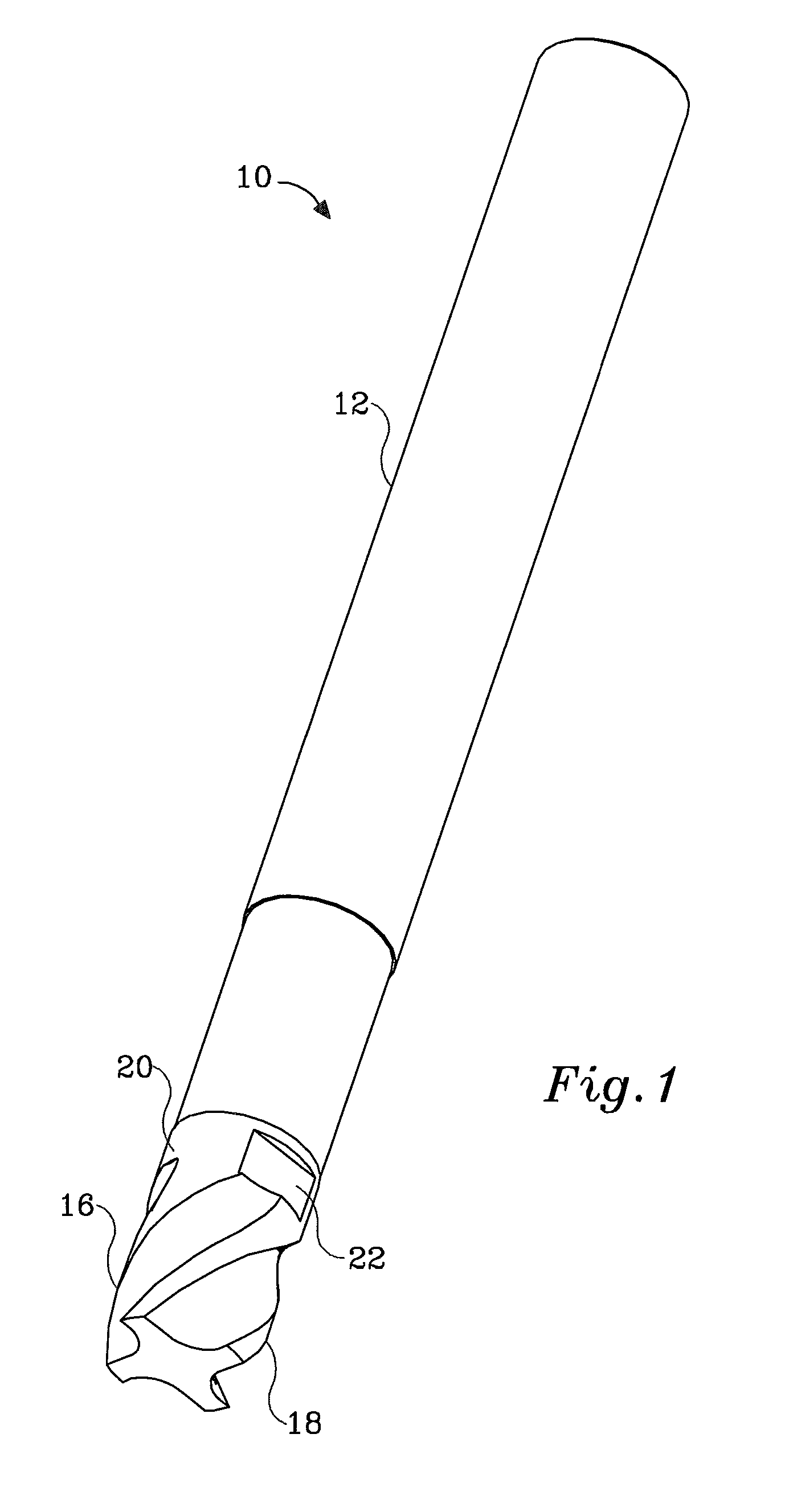
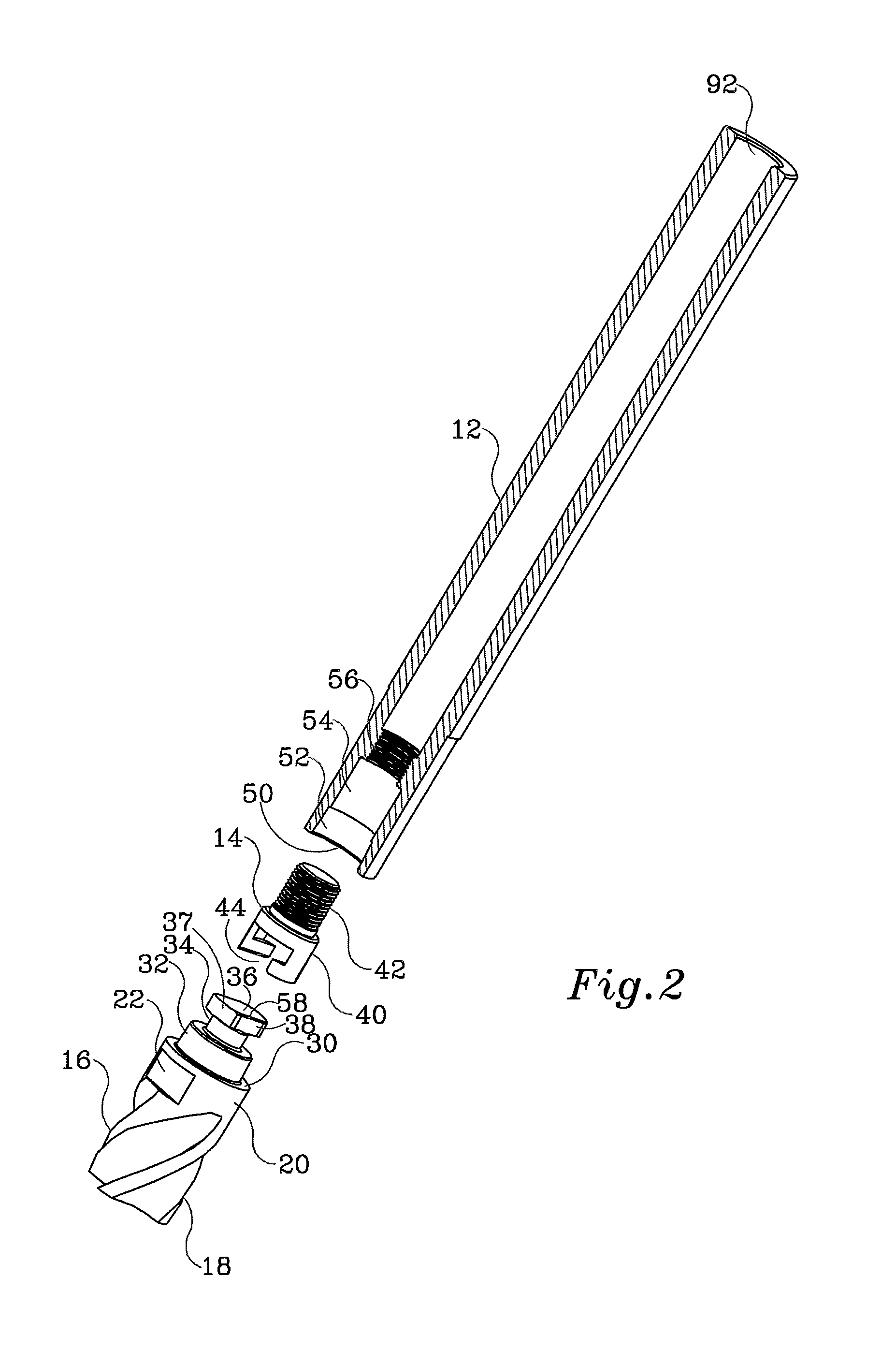
[0033]With reference to FIGS. 1 to 4, there is shown a quick change rotary cutting tool assembly 10, made in accordance with an embodiment of the present invention. The cutting tool assembly 10 has a shank 12, a coupler 14 and a cutter or insert 16, all of which are mutually compatible and independently replaceable. The visible portion of the cutter 16 shown in FIG. 1 when assembled may include an active fluted portion 18 coupled to a short cylindrical portion 20. The cylindrical portion 20 is preferably equipped with at least two opposing parallel flats 22 for allowing the insert to be gripped by a spanner. Although in the figure, the cutter 16 is shown as an end mill, it will be understood that it may equally well be a face mill, rounded tip mill, slitting mill, drill, reamer, or any o...


PUM

PropertyMeasurementUnit
diameteraaaaaaaaaa
shapeaaaaaaaaaa
diameteraaaaaaaaaa

Abstract

A coupler for a quick change rotary cutting tool assembly allowing a cutter to be quickly and releasably coupled to a shank wherein the coupler has a cylindrical portion with a threaded portion to engage the shank and a portion with a transverse groove with undercut walls to form recesses. The cutter has an anchor made as a disk with parallel flats which engage the recesses of the cylindrical portion to releasably secure the cutter to the shank.

Description

FIELD OF THE INVENTION[0001]The present invention relates to rotary cutting tools, more particularly to improvements in a quick change coupler for replaceable insert rotary cutting tools.BACKGROUND OF THE INVENTION[0002]End mills for metal cutting machinery have conventionally been produced as a single unit, comprising a fluted cutting portion and a cylindrical or conical shank portion sized to fit a machine spindle. However the increasing global pricing of modern tool alloys along with recently developed intricate surface treatment make it less economical, as the expensive shank material is wasted. It is therefore becoming common practice to produce a separate cutter (insert) made of high quality alloy or sintered carbide, which is then concentrically attached to the end of a reusable steel shank.[0003]It is highly desirable that the cutter be easily replaced, upon wear, while leaving the shank in the machine spindle, such that no further adjustments are required after cutter repla...

Claims


Application Information

Patent Timeline
Patent Type & Authority Patents(United States)
IPC IPC(8): B23B31/113
CPCB23C2240/04B23C2210/02B23C5/10B23B31/113B23C2210/03Y10T279/17888Y10T407/192Y10T408/95Y10T407/1934Y10T409/30952B23B51/009
Inventor VOLOKH, VLADIMIR, DAVID
Owner KENNAMETAL INC
Why Eureka
Try Eureka