
Method for forming Ni film

a technology of ni film and ni nuclei, which is applied in the direction of coating, chemical vapor deposition coating, metallic material coating process, etc., can solve the problems that the film never permits the removal of such impurities as oxygen, and achieves the reduction of the time required for forming ni nuclei, reducing the time for nucleus forming, and controlling the growth rate of the film

Active Publication Date: 2014-03-11
ULVAC INC
View PDF10 Cites 3 Cited by
  • Summary
  • Abstract
  • Description
  • Claims
  • Application Information

AI Technical Summary

Benefits of technology

[0022]If an Ni film is formed on the surface of an Si substrate using a combination of H2 gas and NH3 gas, as a reducing gas, in place of the conventionally used reducing gas which comprises H2 gas alone, while setting appropriate film-forming conditions, according to the present invention, the following excellent effects can be obtained: The time required for forming Ni nuclei can be controlled (the nucleus-forming time can be reduced); a desired Ni film can be formed at a low temperature; the growth rate of the film can be controlled; the surface morphology of the resulting film can be improved; the concentration of impurities present in the resulting film can be reduced; and the resistance of the resulting film can be lowered. Furthermore, the use of the present invention likewise permits the improvement of the throughput in the process for the fabrication of semiconductor devices. In addition, the method of the present invention also permits the expansion of the temperature range within which the Ni film can be used, and this in turn permits the application of an Ni film in the microfabrication of fine patterns required for the fabrication of a semiconductor device.
[0023]Regarding the foregoing method for the formation of an Ni film, even an Ni film formed by the use of the foregoing reducing gases without any pre-treatment of the surface of the Si substrate can show the foregoing various effects, but if an Ni film is formed on the surface of the Si substrate using the reducing gases after the surface is pre-treated with H2 gas and / or NH3 gas, the aforementioned effects can further be improved. This is because there is such a tendency that if the density of generated Ni nuclei can be increased by the pre-treatment, the time required for the incubation can be reduced.
[0024]Furthermore, the method of the present invention permits the formation of an Ni film having high quality according to the CVD technique and the reduction of the thickness of the resulting Ni film. Accordingly, the Ni film prepared by the method of the present invention can be used in an increased number of steps in the production of semiconductor devices.

Problems solved by technology

In this connection, such an annealing treatment would permit the reduction of the content of impurities such as carbon and nitrogen present in the film, but it never permits the removal of such impurities as oxygen likewise present in the film.

Method used


Image

  • Method for forming Ni film
  • Method for forming Ni film
  • Method for forming Ni film

Examples


example 1

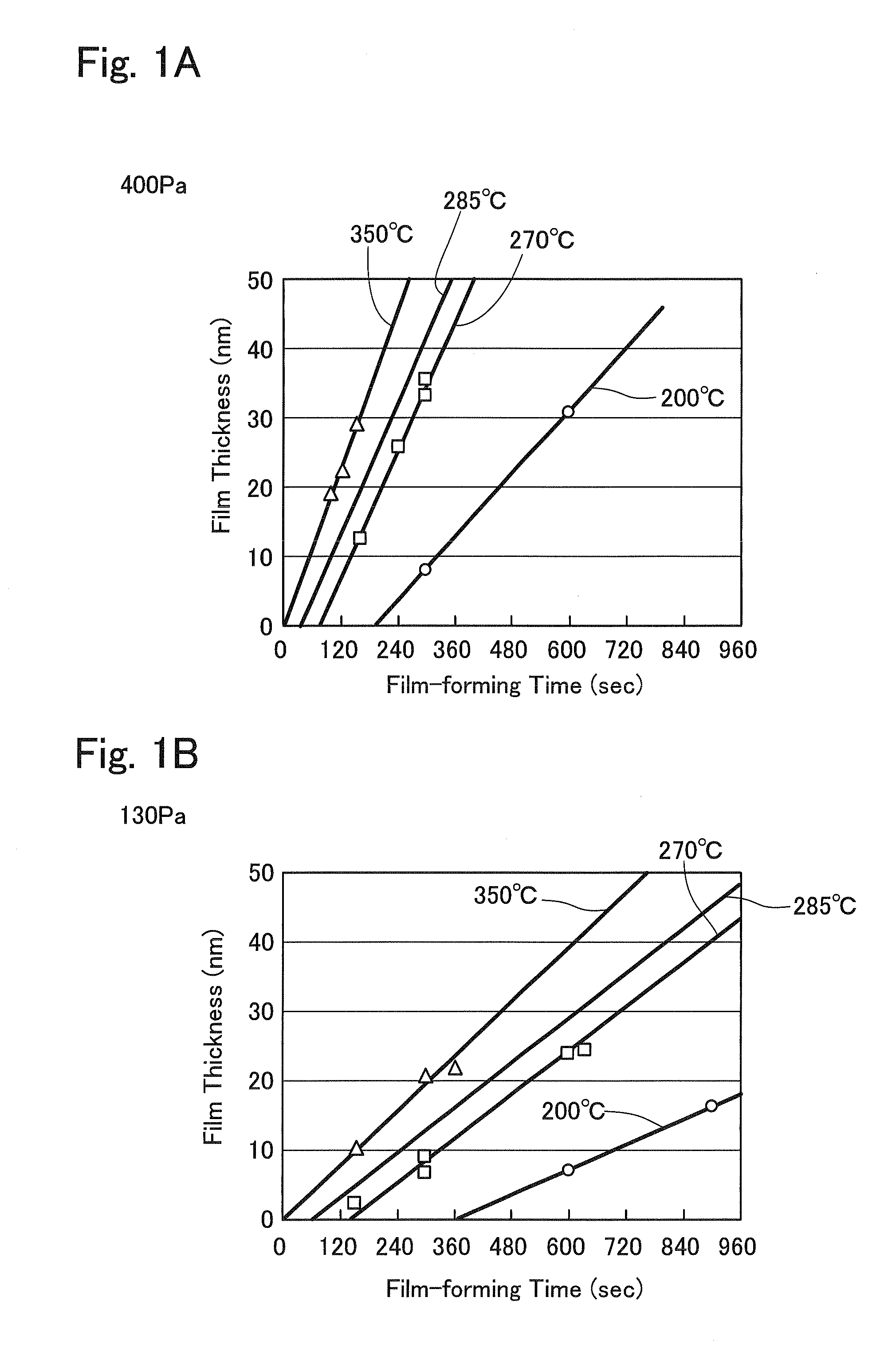
[0044]In this example, an Ni film was formed according to the CVD technique by supplying a nickel alkylamidinate: Ni ((tert-Bu)2-amd)2 (a compound represented by the foregoing general formula (I), in which R is a methyl group (Me); and Bu represents a butyl group) (a product available from Rohm and Haas Company) onto the surface of an Si substrate having a diameter φ of 300 mm, from which the oxide or natural oxide formed on the surface of the substrate through the natural oxidation had been removed, in a constant flow rate, while using, as reducing gases, 200 sccm or 150 sccm of H2 gas and 200 sccm or 150 sccm of NH3 gas and setting the film-forming pressure at a level of 130 Pa or 400 Pa and setting the film-forming temperature (the substrate temperature) at a level of 200° C., 270° C., 285° C. or 350° C.

[0045]In this respect, the Ni films thus formed was inspected for the relation between the film-forming time (second; sec) and the thickness (nm) of the resulting film and the res...

example 2

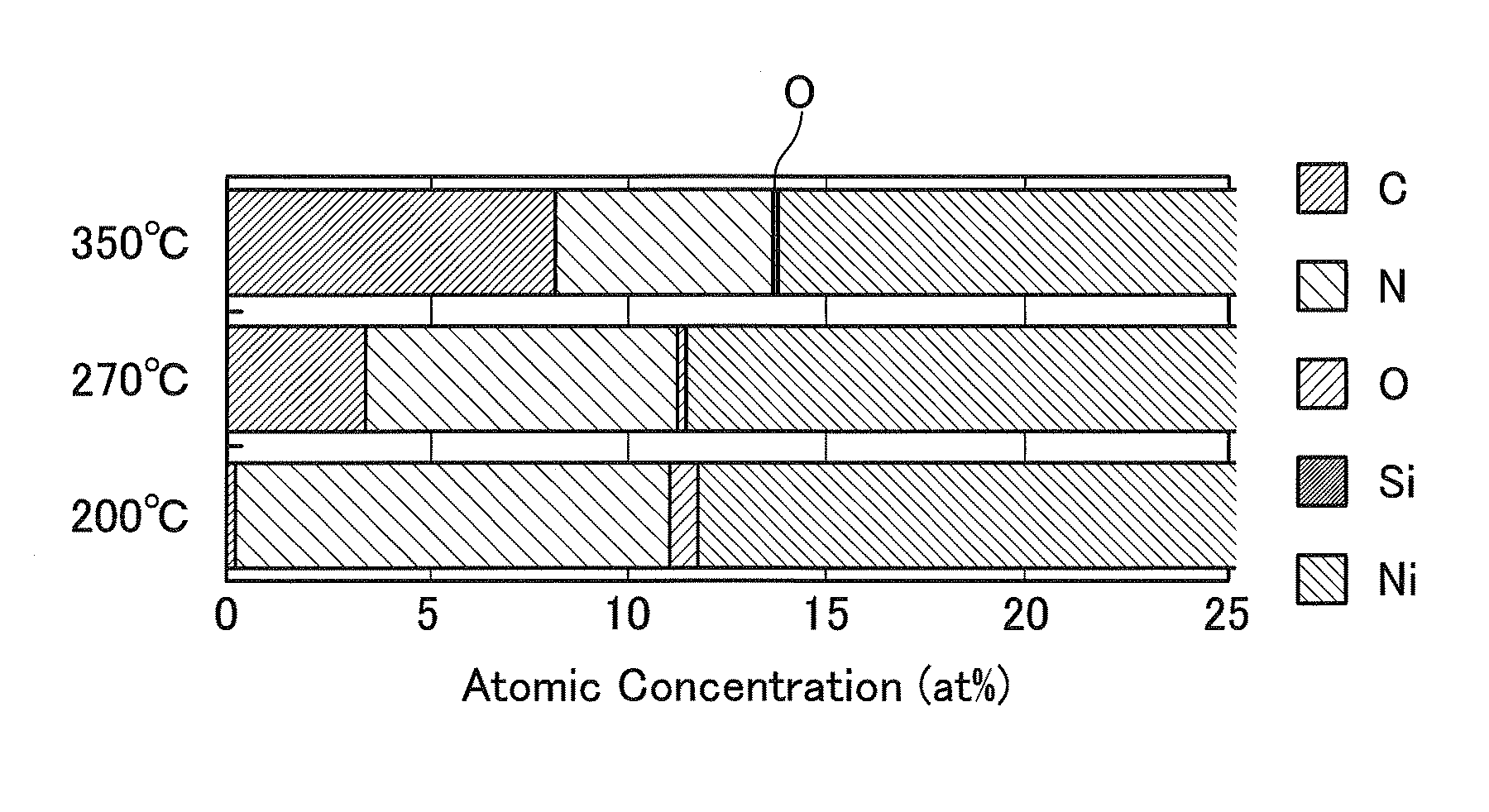
[0048]In this Example, the nickel alkylamidinate disclosed in Example 1 was used under the same conditions, and the same procedures used in Example 1 were repeated by using H2 gas and NH3 gas as reducing gases in amounts of 200 sccm and 200 sccm, or 150 sccm and 150 sccm; setting the film-forming pressure at 400 Pa; and setting the substrate temperature at 200° C., 270° C., 285° C. or 350° C. to thus form each corresponding Ni film. Each of the resulting films was inspected and evaluated for the concentrations of atomic components included in the resulting Ni film, according to the SIMS technique.

[0049]The results thus obtained are shown in FIG. 2. More specifically, FIG. 2 shows the concentrations (at %) of atomic components present in the Ni films produced at the foregoing respective temperatures, while using the H2 gas and the NH3 gas in amounts of 200 sccm and 200 sccm respectively. From the results shown in FIG. 2, it could be recognized that the nitrogen concentration is reduc...

example 3

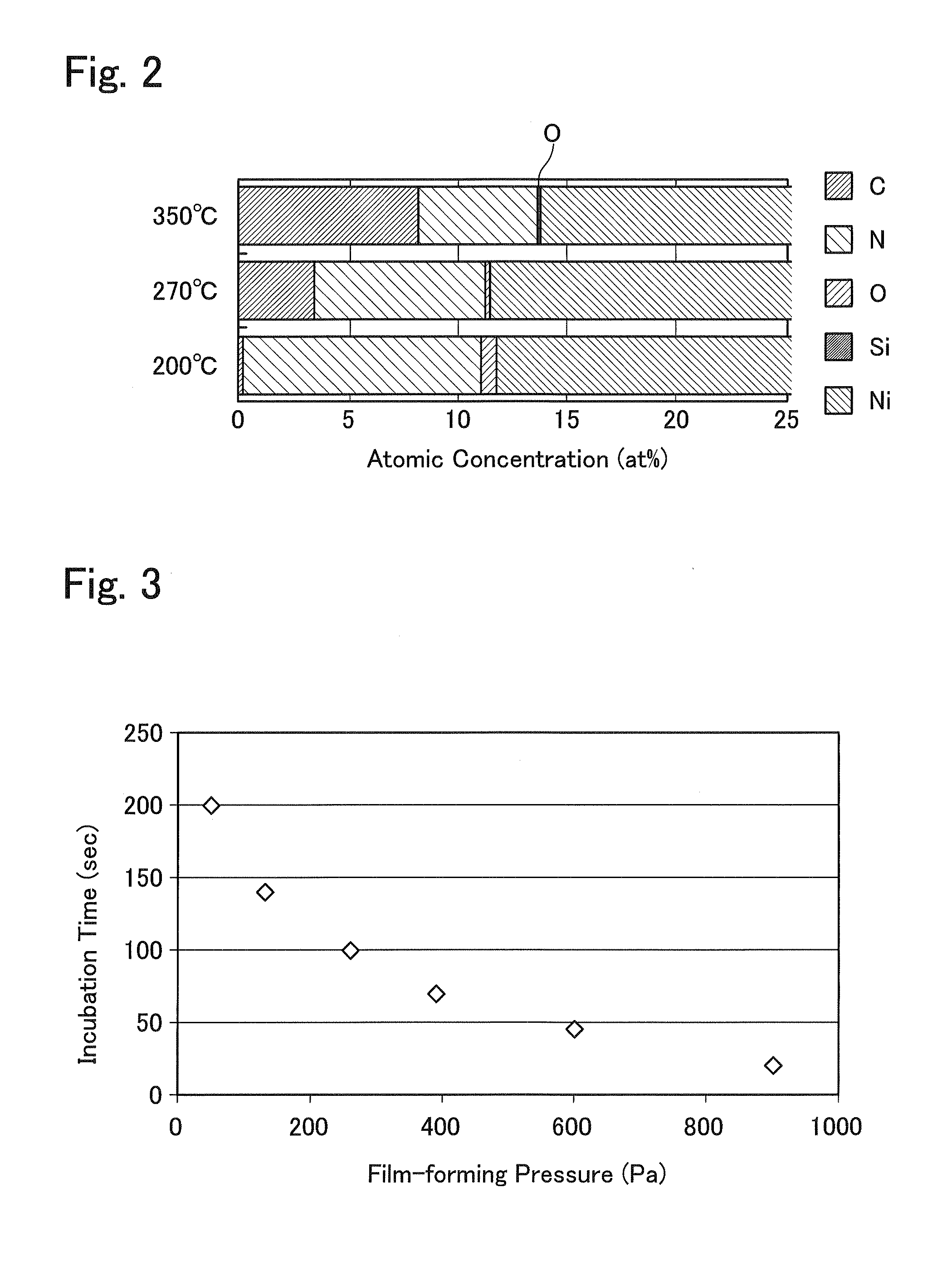
[0052]In this Example, the nickel alkylamidinate disclosed in Example 1 was used under the same conditions, and the same procedures used in Example 1 were repeated by using H2 gas and NH3 gas as reducing gases in amounts of 200 sccm and 200 sccm, or 150 sccm and 150 sccm, respectively; setting the substrate temperature at 285° C.; and changing the film-forming pressure so that it falls within the range of from about 50 Pa to about 900 Pa to thus form each corresponding Ni film.

[0053]The resulting films were inspected or evaluated for the relation between the film-forming pressure and the incubation time (second; sec), wherein the films were those produced using the H2 gas and the NH3 gas each in an amount (flow rate) of 200 sccm and the substrate temperature of 285° C. and the results thus obtained are plotted on FIG. 3.

[0054]As will be seen from the data plotted on FIG. 3, the incubation time is decreased as the film-forming pressure increases. It would be assumed that such a resul...


PUM

PropertyMeasurementUnit
temperatureaaaaaaaaaa
pressureaaaaaaaaaa

Abstract

A method for the formation of an Ni film is herein disclosed, which comprises the steps of maintaining the temperature of an Si substrate at a desired level in a vacuum chamber; introducing, into the vacuum chamber, a nickel alkylamidinate (in this organometal compound, the alkyl group is a member selected from the group consisting of a methyl group, an ethyl group, a butyl group and a propyl group), H2 gas and NH3 gas; and then forming an Ni film according to the CVD technique, wherein the film-forming temperature is set at a level between higher than 280° C. and not higher than 350° C.

Description

TECHNICAL FIELD[0001]The present invention relates to a method for forming an Ni film and more particularly to a method for forming an Ni film, which makes use of specific film-forming conditions.BACKGROUND ART[0002]Recently, the techniques for micronizing semiconductor devices have been advanced and there has been such a remarkable tendency that a semiconductor device has a three-dimensional structure. As a result, there has widely been used a technique which makes use of a silicide film formed on, for instance, the bottoms of trenches and holes, which are formed on or through a substrate, and the side walls thereof. For this reason, the need for the achievement of a high coverage characteristics (step-coverage characteristics) of such a silicide film with respect to these bottoms and sides has also become higher and higher.[0003]As metals for forming such a silicide film, there have conventionally been used, for instance, Ti, Co and Ni. The sputtering technique has conventionally ...

Claims


Application Information

Patent Timeline
Patent Type & Authority Patents(United States)
IPC IPC(8): H01L21/31H01L21/469
CPCH01L21/28562C23C16/18H01L21/28556H01L21/28518C23C16/06H01L21/0262
Inventor UEHIGASHI, TOSHIMITSUHIGUCHI, YASUSHIISHIKAWA, MICHIOUSHIKAWA, HARUNORIHANADA, NAOKI
Owner ULVAC INC
Learn More