Electron gun

a technology of electrostatic lens and arc-shaped arc-shaped rod, which is applied in the field of electrostatic lens, can solve the problems of difficult reduction of aberration of electrostatic lens, inability to achieve high performance, and significantly decrease in brightness (effective brightness). , to achieve the effect of reducing the incidental electrostatic lens action, small aberration, and high brightness

Inactive Publication Date: 2014-03-11
HITACHI HIGH-TECH CORP
View PDF22 Cites 0 Cited by
  • Summary
  • Abstract
  • Description
  • Claims
  • Application Information

AI Technical Summary

Benefits of technology

[0026]The present invention can provide an electron gun having a function of converging an electron beam using a magnetic field, the electron gun which is capable of reducing an incidental electrostatic lens action and has small aberration and high brightness.

Problems solved by technology

Unfortunately, in this electron gun, the total amount of current which can be taken out is smaller than that of other types of electron sources such as a Schottky electron source, and if a large current is to be taken out, it is necessary to use an electron beam which is emitted at a wide angle from a chip.
For example, this electron gun is disadvantageous in that, if several percent of the total amount of current emitted from the chip (cathode) is to be taken out, the brightness (effective brightness) considerably decreases due to an influence of the aberration of the electrostatic lens.
Such aberration of the electrostatic lens is difficult to reduce.
For reasons to be described later, even if the structures of the known examples are applied to the cold cathode field-emission electron gun without any change, high performance cannot be achieved.

Method used


Image

  • Electron gun
  • Electron gun
  • Electron gun

Examples


embodiment 1

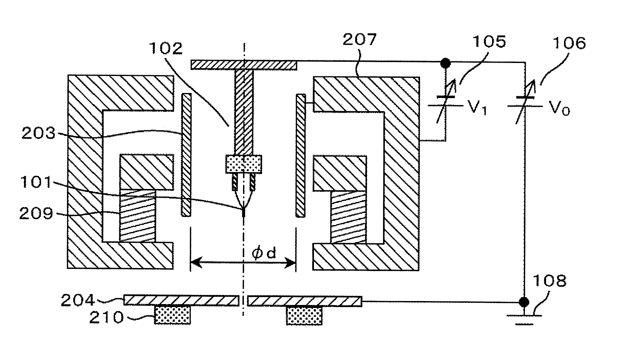
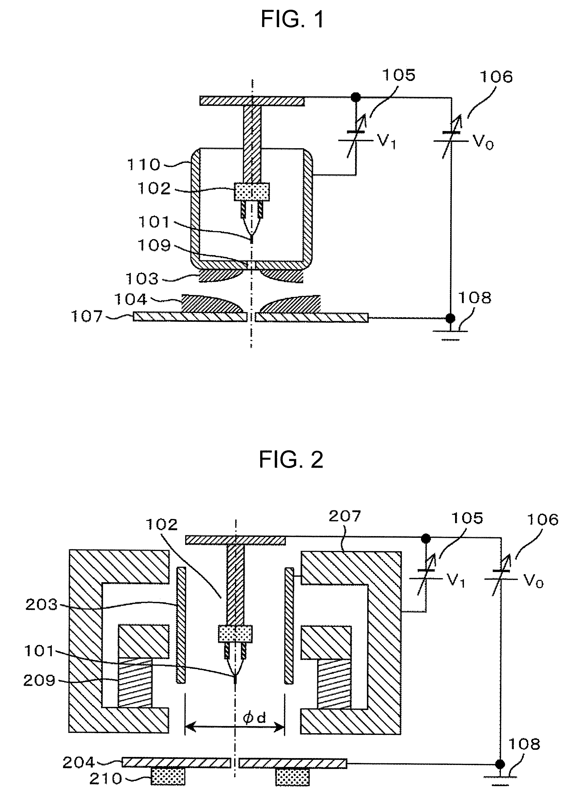
[0038]FIG. 2 illustrates a mode of an immersion-type cold cathode field-emission electron gun as an exemplary embodiment of the present invention.

[0039]FIG. 2 illustrates the structure of the electron gun according to the present invention. An electron source 101, an electron source holding part 102, an extraction electrode 203, an anode 204, a magnetic path 207, and a permanent magnet 209 are disposed in a vacuum container (not illustrated), and the inside of the vacuum container is maintained at an ultrahigh vacuum of approximately 10−8 Pa. A potential V0 (negative potential) is applied to the electron source 101 by an acceleration power supply 106 with reference to a ground part 108. Further, a voltage V1 (positive voltage, several kilovolts) is applied to the extraction electrode 203 by an extraction power supply 105 with reference to this electron source potential. Field emission is caused by the potential (V1), and an electron beam (having an energy of V0−V1) is emitted from t...

embodiment 2

[0047]A modified example of Embodiment 1 is described. Even if the shape of the extraction electrode is not completely cylindrical and the extraction electrode has a slight aperture structure, it is possible to achieve the object to converge an electron beam mainly by the magnetic field lens while suppressing the converging force and aberration of the electric field lens to be low.

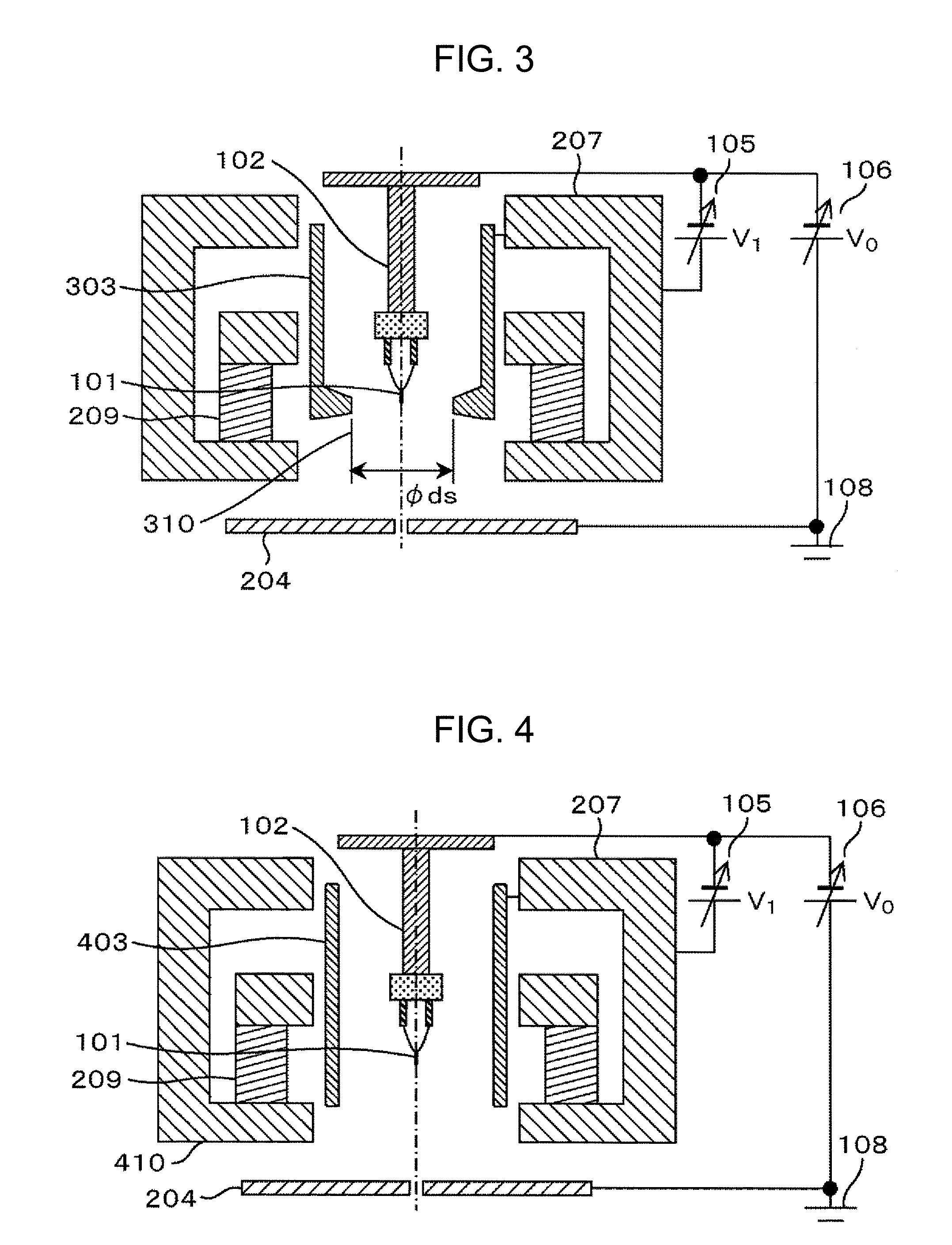
[0048]FIG. 3 illustrates the case where the extraction electrode does not have a cylindrical shape. In FIG. 3, a protruding part is provided to such an extent that an extraction electrode 303 does not produce the lens action of the electric field. It is desirable that an inner diameter 310 of the smallest part of the extraction electrode aperture at this time be equal to or larger than 2 mm.

[0049]FIG. 10 shows example theoretical analysis results obtained by assuming shapes, in which theoretical analysis results when an inner diameter ds of the smallest part is set to 1 mm and 2 mm are overlaid on the grap...

embodiment 3

[0050]Further, regardless of whether the anode-side end of the extraction electrode is positioned on the anode side or on the cathode side with respect to the electron source, it is possible to achieve the object to converge an electron beam mainly by the magnetic field lens while suppressing the converging force and aberration of the electric field lens to be low.

[0051]FIG. 4 and FIG. 5 each illustrate another embodiment relating to the position of the anode-side end of the extraction electrode.

[0052]In FIG. 4, an extraction electrode 403 is extended toward the anode 404 so as to be longer than the extraction electrode 203 in FIG. 2. The extraction electrode 403 may be extended toward the anode 204 beyond a magnetic path lower surface 410 so as to hide the entire permanent magnet 209 and magnetic path 207 from the electron beam path. Even in this case, the electric field lens effect is not considerably large. As illustrated in FIG. 5, the anode 204 side-end of an extraction electro...


PUM


Abstract

The present invention has an object to provide a cold cathode field-emission electron gun with low aberration, to thereby provide a high-brightness electron gun even in the case of a large current. The present invention provides a field-emission electron gun which extracts an electron beam from a cathode and converges the extracted electron beam, the field-emission electron gun including: a magnetic field lens which is provided such that the cathode is disposed inside of a magnetic field of the lens; and an extraction electrode for extracting electrons from the cathode, the extraction electrode being formed into a cylindrical shape without an aperture structure. The present invention can provide an electron gun having a function of converging an electron beam using a magnetic field, the electron gun which is capable of reducing an incidental electrostatic lens action and has small aberration and high brightness.

Description

RELATED APPLICATIONS[0001]This application is the U.S. National Phase under 35 U.S.C. §371 of International Application No. PCT / JP2010 / 002684, filed on Apr. 14, 2010, which in turn claims the benefit of Japanese Application No. 2009-123684, filed on May 22, 2009, the disclosures of which Applications are incorporated by reference herein.TECHNICAL FIELD[0002]The present invention relates to an electron gun, and more particularly, to a cold cathode field-emission (Cold-FE) electron gun which generates a high-brightness electron beam.BACKGROUND ART[0003]An electron microscope irradiates a material to be observed (sample) with an electron beam emitted from an electron gun while controlling the electron beam using an electron optical system such as an electron lens and a deflector. Then, the principle of the electron microscope is to detect transmission electrons transmitted through the irradiated sample and reflection electrons and secondary electrons generated by the interaction betwee...

Claims


Application Information

Patent Timeline
Patent Type & Authority Patents(United States)
IPC IPC(8): H01J1/50
CPCH01J2237/06341H01J37/141H01J37/063H01J2237/065H01J2237/06316H01J2237/26H01J37/073
Inventor ICHIHASHI, MIKIOONISHI, TAKASHIWATANABE, SHUNICHITAMURA, KEIJI
Owner HITACHI HIGH-TECH CORP
Why Eureka
Try Eureka