Glow plug placement in a diesel engine

a technology for diesel engines and glow plugs, which is applied in the direction of machines/engines, lighting and heating apparatus, electric control, etc., can solve the problems of little fuel travel, too lean rebound mixture, and compromise the strength of the cylinder head, so as to achieve less distortion and weakening of metal, no valve size nor strength at the valve bridge need to be compromised, and the effect of less distortion and weakening

Active Publication Date: 2014-03-18
FORD GLOBAL TECH LLC
View PDF22 Cites 14 Cited by
  • Summary
  • Abstract
  • Description
  • Claims
  • Application Information

AI Technical Summary

Benefits of technology

[0010]A combustion chamber is disclosed which is delimited by a cylinder wall, a cylinder head, and a piston reciprocating within the cylinder wall. The cylinder head has an injector centrally mounted. The injector has a plurality of injector nozzles arranged peripherally around a tip of the injector. When the injector is commanded to open when the piston is near a top center position, fuel jets emanate from the nozzles toward the walls of the piston bowl. The piston bowl has a feature which causes a first portion of the fuel to be directed upwardly toward the cylinder head and then along the cylinder head back toward the injector. A second portion of the fuel is directed downwardly into the piston bowl. A third portion of the fuel is directed upwardly toward the cylinder head and then outwardly toward the cylinder wall. The glow plug is mounted in the cylinder head such that a tip of the glow plug extends into the combustion chamber within a region of vapor formed from the first portion of fuel after redirection by the cylinder bowl feature. According to an embodiment of the present disclosure, a 4-valve-per-cylinder cylinder head has two adjacent intake ports and two adjacent exhaust ports. The injector is centrally mounted. The glow plug is mounted in between two adjacent ports outboard of the minimum thickness portion of the valve bridge between the two adjacent ports. The surface of the piston bowl has a vertical section substantially parallel to the cylinder axis. The tip of the glow plug is located just slightly towards the center of the cylinder with respect to the vertical section. The glow plug is canted such that it comes out of the cylinder head and into the combustion chamber at the location outboard of the minimum separation point between adjacent ports while the tip is inboard of the piston's vertical section. In one embodiment, the glow plug is mounted in between an intake port and an adjacent exhaust port with the glow plug mounted slightly closer to the intake valve, as the metal temperature closer to the intake valve is at a lower temperature, thus less distortion and weakening of the metal in that region. In yet another alternative, the glow plug is mounted in the cylinder head outboard of the valve bridge.
[0011]According to an embodiment of the disclosure, the cylinder head strength, and hence the maximum pressure rating of the engine, is not compromised with the glow plug installed outboard of the narrowest point of the valve bridge. A combustion chamber with such orientation of the glow plug develops about 10% higher peak pressure than engines having the glow plug mounted within the valve bridge near the narrowest point of the valve bridge. Similarly, glow plug positioning according to the present disclosure accommodates larger valve diameters relative to prior art configurations with valve diameter constrained by desired strength and glow plug placement. According to the present disclosure, neither valve size nor strength at the valve bridge need be compromised.
[0013]By placing the glow plug farther outboard in an engine with a particular piston bowl design, the glow plug interacts with the fuel twice, rather than once according to the prior art. With a particular piston bowl, the fuel jets interact with a substantially vertical surface of the combustion bowl causing some of the fuel spray to move upwards toward the cylinder top and some to move downwards into the bowl. Of the fuel moving upwards, some of the fuel moves back inward toward the injector and some of the fuel moves outward toward the cylinder walls. The portion of the fuel that is directed upward and then inward envelops the glow plug. In the glow plug location disclosed, the tip of the glow plug is in the vicinity of the fuel as it traverses the glow plug on a first pass after being injected and then again on the rebound when it is directed by the piston bowl geometry. It has been found that the cold start is improved by the fuel coming into contact with the glow plug twice as opposed to simply once. In the prior art location, the glow plug is so far away from the piston bowl edge, that little fuel travels back to the glow plug location after interacting with the piston bowl edge and the rebounded mixture is too lean to burn. By allowing the glow plug two opportunities to interact with a combustible fuel mixture, cold start performance is improved. In most diesel engines, cold start performance dictates a higher compression ratio than that which yields best efficiency. By improving cold start performance, a slight reduction in compression ratio is possible thereby increasing fuel efficiency.
[0014]In a twisted-port engine with intake swirl, there is a concern that by putting the glow plug outboard of the minimum separation of the valve bridge that the fuel jet bound for the glow plug would be displaced sufficiently that the glow plug would no longer be near a combustible mixture of the fuel jet. However, in one application, this was not found to be a problem, even though as much as 10 degrees of angular rotation was experienced at some operating conditions (about only 5 degrees of rotation at the distance of the glow plug from the central axis). And, as mentioned above, appropriate placement of the glow plug near the path of the fuel jet emitted from the injector and redirected by the piston bowl affords two opportunities for the glow plug to heat and ignite fuel.
[0015]Typical diesel fuel injectors spray liquid fuel out of multiple nozzles at high pressure into hot air in the combustion chamber. Because the pressure drop across the injector nozzles is high, the liquid fuel is injected at high velocity causing the fuel to atomize into very fine droplets and to entrain air as it travels from the injector toward the cylinder walls. Because of the high temperature of the compressed gases in the cylinder, the small droplet size, and the mixing with the air, the droplets rapidly vaporize so that before the fuel jet travels to the cylinder walls, the jet is a mixture of fuel vapor and air with no droplets remaining. Thus, yet another advantage of placing the glow plug farther away from the injector than customary in the prior art is that it is even less likely that a liquid droplet impacts the glow plug.

Problems solved by technology

In prior art on engines with 4-valve heads, the glow plug is placed near the injector in the valve bridge area (necked region in between adjacent valves), which compromises the strength of the cylinder head.
However, because a cylinder head with two valves has space for a glow plug, there is no concomitant advantage of chamber strength by such glow plug placement per the present development.
In the prior art location, the glow plug is so far away from the piston bowl edge, that little fuel travels back to the glow plug location after interacting with the piston bowl edge and the rebounded mixture is too lean to burn.
However, this combustion system is quite different than a typical diesel combustion system in a number of ways.

Method used


Image

  • Glow plug placement in a diesel engine
  • Glow plug placement in a diesel engine
  • Glow plug placement in a diesel engine

Examples


Embodiment Construction

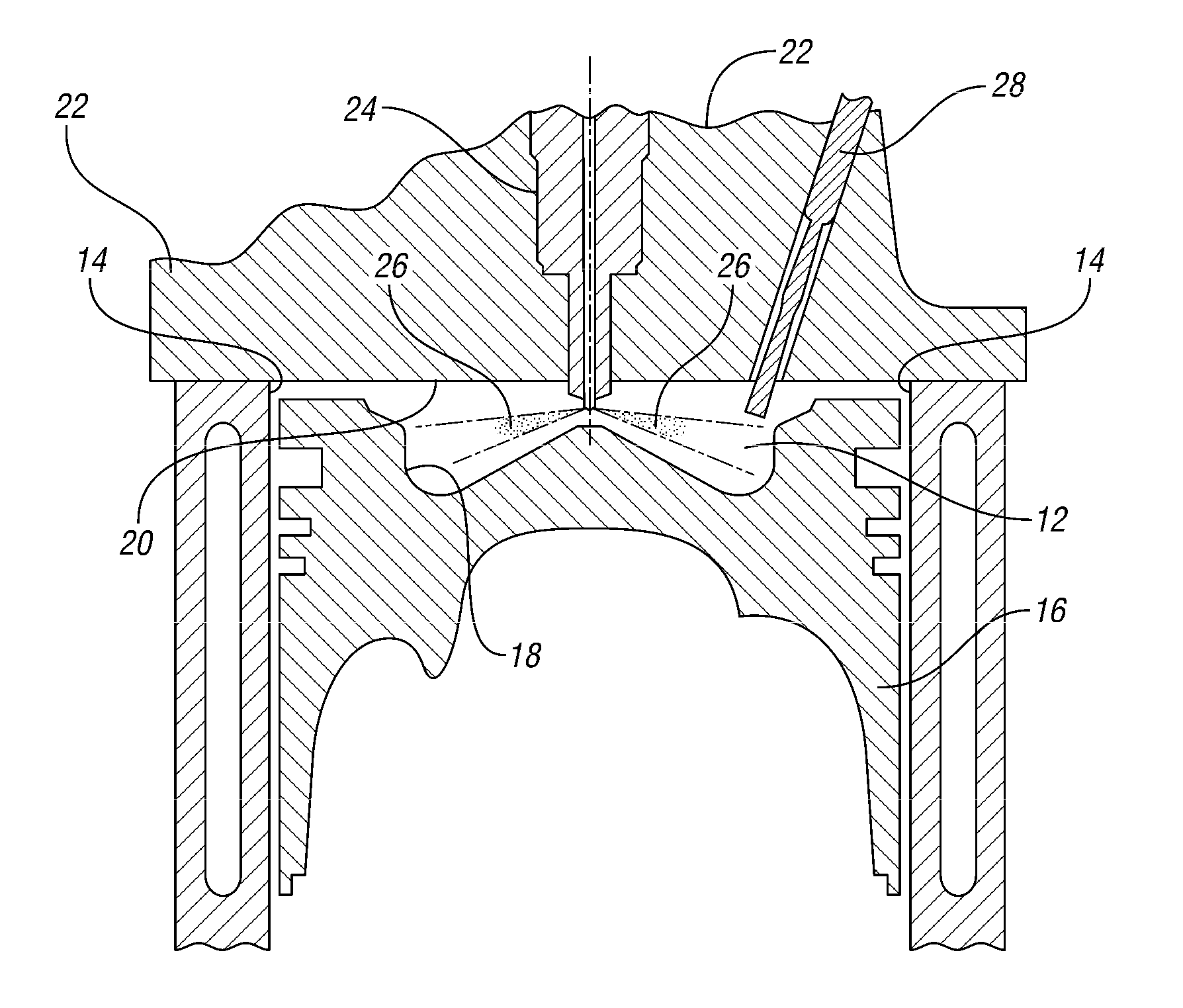
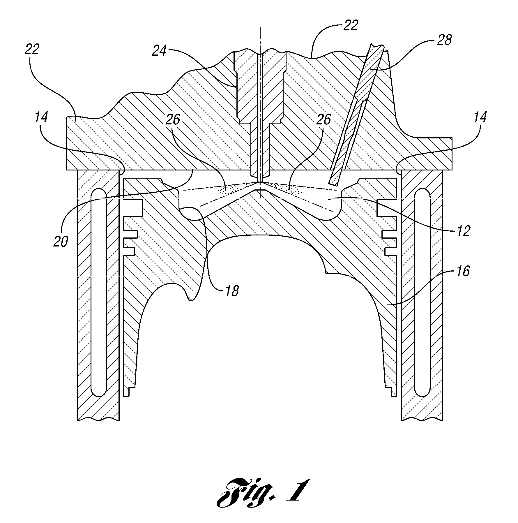
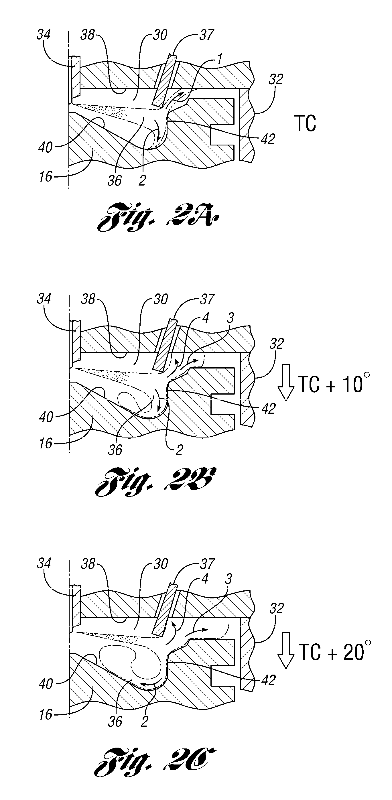
[0022]As those of ordinary skill in the art will understand, various features of the embodiments illustrated and described with reference to any one of the Figures may be combined with features illustrated in one or more other Figures to produce alternative embodiments that are not explicitly illustrated or described. The combinations of features illustrated provide representative embodiments for typical applications. However, various combinations and modifications of the features consistent with the teachings of the present disclosure may be desired for particular applications or implementations. The representative embodiments used in the illustrations relate to placement of a glow plug in a 4-valve-per-cylinder engine that is outboard of the narrowest section of the valve bridge in between adjacent valves. Those of ordinary skill in the art may recognize similar applications or implementations consistent with the present disclosure, e.g., ones in which components are arranged in a...


PUM


Abstract

A four-valve per cylinder engine has two intake valves, two exhaust valves and a centrally located fuel injector. Between each adjacent pair of valves is a valve bridge with a point of minimum separation between adjacent valves. In the present disclosure, the glow plug port is defined in the cylinder top at a location outboard of the minimum separation between adjacent and at a depth which is tangent to an edge of a fuel jet emanating the injector. By placing the glow plug farther outboard than found in the prior art, the glow plug contacts the fuel as it comes out of the injector and as it rebounds off a feature of the piston bowl.

Description

BACKGROUND[0001]1. Technical Field[0002]The present disclosure relates to combustion chambers in direct-injection diesel engines.[0003]2. Background Art[0004]Because of the combustion nature of a diesel engine (compression ignition) cold start and cold operation performance are the hardest requirements for a diesel engine. These requirements drive diesel engines to use cold start aids, one such aid is having the combustion chambers of diesel engines equipped with glow plugs to aid cold start performance, thereby minimizing misfire and white smoke (unburned fuel) during operation directly after a cold start. Optimum compression ratios for best efficiency in real world engines occur at a compression ratio of 15 to 1. To further help improve this cold start performance and operation; historically compression ratios of diesel engines were raised to levels much higher than the optimum of 15 to 1 to increase compression temperatures in the cylinder during cold operation. With the advent o...

Claims


Application Information

Patent Timeline
Patent Type & Authority Patents(United States)
IPC IPC(8): F02B3/00F23Q7/00
CPCY02T10/123F02B23/0696Y02T10/125F02D41/064F02B2275/14F02P19/02F02B23/0657F02B23/0669F02B23/0651F02B23/0693F02B3/06Y02T10/12
Inventor IVES, DAVID CURTISFULTON, BRIEN LLOYDKURTZ, ERIC MATTHEWOPPERMAN, BRADLEY DAVIDSTYRON, JOSHUA PUTMANMORGAN, PATRICK BRIANATZWANGER, MARTIN JOHANNES
Owner FORD GLOBAL TECH LLC
Why Eureka
Try Eureka