
High-pressure fuel supply pump and the manufacturing method

a technology of high-pressure fuel supply and manufacturing method, which is applied in the direction of fuel injecting pump, machine/engine, non-electric welding apparatus, etc., can solve the problems of insufficient fluid sealability and insufficient connection strength, unsuitable connection method for magnetic circuit, and inability to maintain initial design dimensions, etc., to achieve strong vibration resistance, high sealing reliability, and large welding force

Inactive Publication Date: 2014-03-18
HITACHI LTD
View PDF11 Cites 8 Cited by
  • Summary
  • Abstract
  • Description
  • Claims
  • Application Information

AI Technical Summary

Benefits of technology

The present invention relates to a method for manufacturing a high-pressure fuel supply pump. The method involves the use of laser welding and diffusion welding to create a sealing connection between the pump housing and the cylinder or fixing ring, as well as between the pump housing and the intake or discharge joint. The method has advantages such as faster plastic flow, increased frictional resistance, and ensuring a sealing distance and area great enough for sealing between the fuel and the atmosphere. The method also allows for an automatic aligning effect during the welding process, maintaining the design dimensions of the pump and the installation hole. Additionally, the method provides a stronger pump against vibration and requires no special sealing mechanism for the intake or discharge joint.

Problems solved by technology

These structures, however, have the problems of insufficient fluid sealability and insufficient connecting strength.
In addition, laser welding, in particular, has the problem that since a change in the composition of the material itself due to heat causes magnetic characteristics to change randomly before and after connecting, this connecting method is unsuitable for magnetic circuits.
Furthermore, laser welding causes the metals to suffer dimensional changes due to thermal deformation before and after connecting, and thus makes it impossible to maintain initial design dimensions.

Method used


Image

  • High-pressure fuel supply pump and the manufacturing method
  • High-pressure fuel supply pump and the manufacturing method
  • High-pressure fuel supply pump and the manufacturing method

Examples


embodiment

Sixth Mode of Embodiment

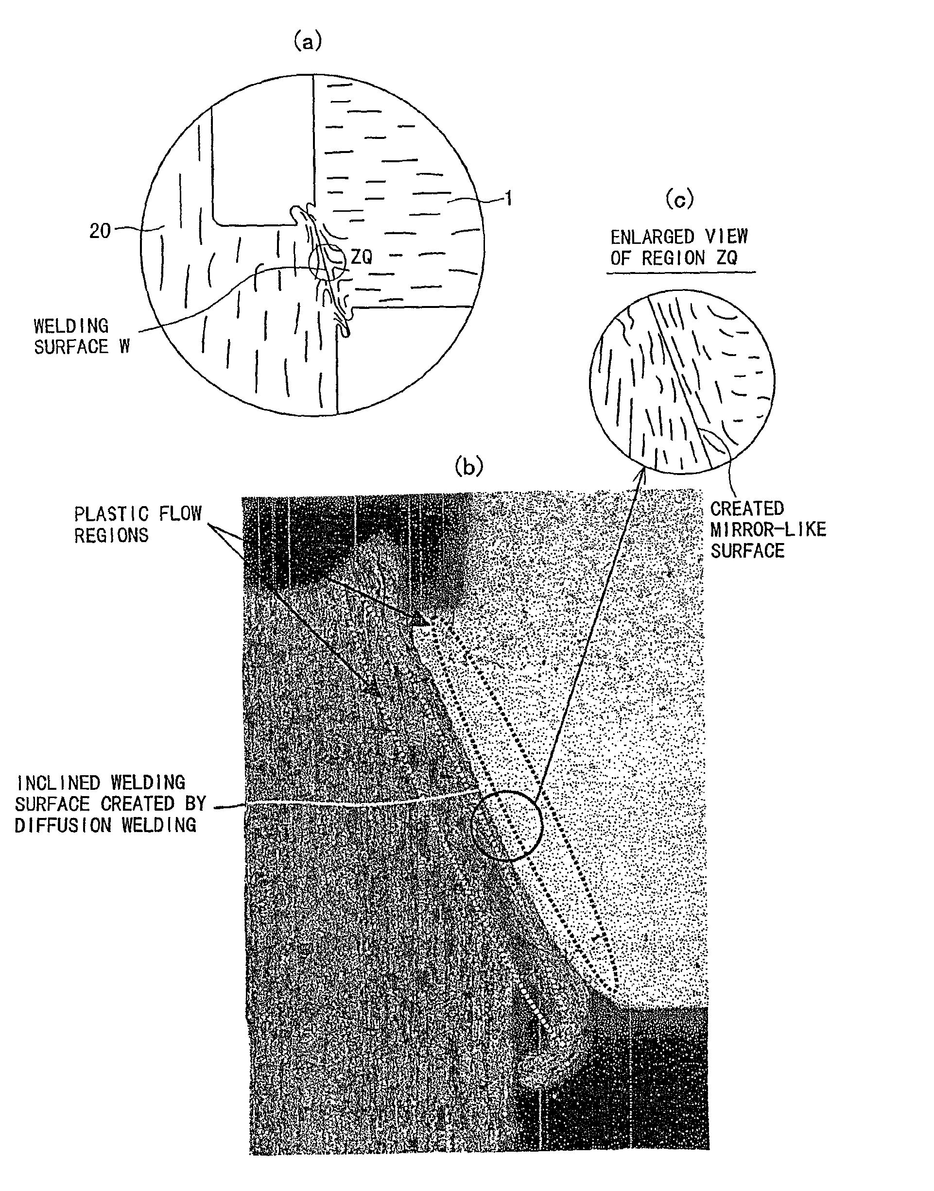
[0133]The welded structure of two metals according to the first mode of embodiment, wherein both metals are formed of a material different from each other in hardness, the weld surface of the harder metal is formed into a convex shape, and the weld surface of the softer metal is formed into a concave shape.

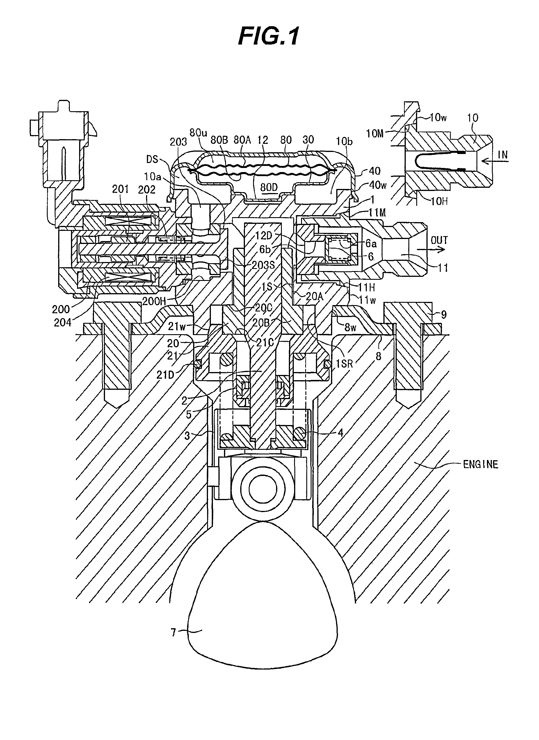
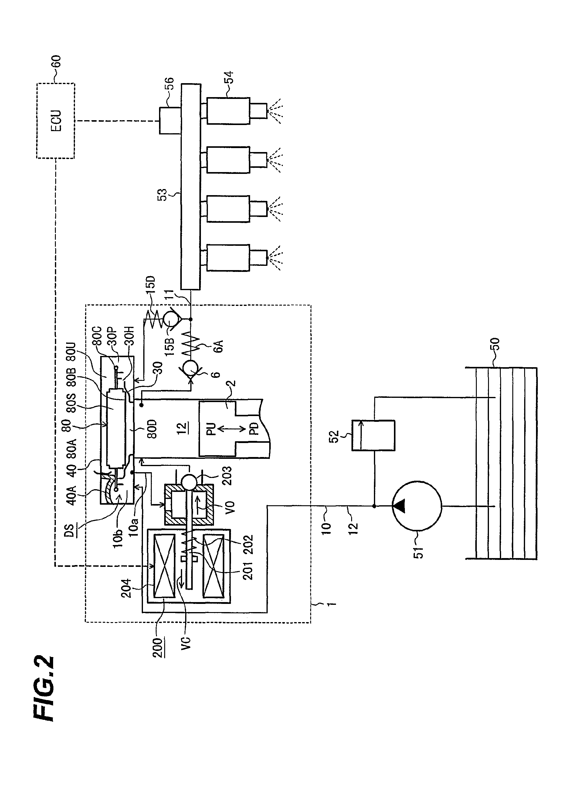
[0134]How the welded structure is constructed at various connections in the high-pressure fuel supply pump shown in FIG. 1 will be next described for each of the connections.

[0135]1) First, the connection 10w between the intake joint 10 and the pump housing 1 is described below per FIG. 1.

[0136]The intake joint 10 has, at a distal end thereof, a tapered weld surface 10M formed of a part of a conical surface.

[0137]Welding between the intake joint 10 and the pump housing 1 is achieved using the welding method discussed earlier per FIGS. 3 and 4.

[0138]More specifically, the intake joint 10 and the pump housing 1 are joined together by applying a high voltage w...

first embodiment

[0285]A welded structure formed in solid-state welded form by first providing an inclined abutting surface upon both of two metals to be joined together by resistance welding, then after connecting an electrode of different polarity to each metal and heating both metals with an electric current and frictional pressurizing, creating an alloy zone (diffusion zone) at a contact interface of that connection.

second embodiment

[0286]The welded structure according to the first embodiment, wherein the abutting surfaces are formed into an inclined annular shape and both metals are joined together so as to match respective central axes to each other along the inclined surfaces when pressurized and joined.


PUM

PropertyMeasurementUnit
voltageaaaaaaaaaa
pressureaaaaaaaaaa
axial relative displacementsaaaaaaaaaa

Abstract

In order to provide a welded structure of and welding method for two metallic parts fitted together at a tubular section in a high-pressure fuel supply pump, an electric current is supplied to any of the welding connection surfaces formed between a pump housing and cylinder in a high-pressure fuel supply pump, between the pump housing and an installation flange, between the pump housing and an intake or discharge joint, between the pump housing and a pulsation-absorbing damper cover, between the pump housing and a relief valve mechanism, and between the pump housing and an electromagnetically driven intake valve mechanism. The two sections are pressed against each other to generate, along the connection surface, a plastic flow not causing melting or fusion due to heat, and form a diffusion-weld region at the connection surface by using the plastic flow and the application of the pressure.

Description

BACKGROUND OF THE INVENTION[0001]1. Field of the Invention[0002]The present invention relates generally to high-pressure fuel supply pumps and their manufacturing methods. More particularly, the invention relates to a welded structure in which two metals, after being fitted at an annular or tubular section, are tightly connected together at the fitting-in portions by welding.[0003]2. Description of the Related Art[0004]JP-A-2005-342782 and JP-A-2004-17048 discloses techniques in which a tubular metal is fitted into a hole of another tubular metal before the two metals are connected together by welding.[0005]According to the above Publications, the two metals are connected together by supplying an electric current while applying pressure to the fitting-in portions.[0006]Meanwhile, there are other known different techniques for realizing a welded structure comprising a cylinder of a high-pressure fuel supply pump and a housing of the pump. That is, International Publication Pamphlet W...

Claims


Application Information

Patent Timeline
Patent Type & Authority Patents(United States)
IPC IPC(8): F04B19/00
CPCF02M59/485B23K33/008B23K2203/02B23K33/006F02M59/48F04B53/168F02M59/02B23K11/16B23K11/26B23K2201/04F04B1/0404B23K20/023F02M2200/8084B23K2101/04B23K2103/02
Inventor MUNAKATA, AKIHIROMACHIMURA, HIDEKIHOSOKAWA, KAZUTAKA
Owner HITACHI LTD
Learn More