Spring terminal, in particular a front terminal

a technology of spring terminal and front terminal, which is applied in the direction of coupling device details, coupling device connections, contact members penetrating/cutting insulation/cable strands, etc., can solve the problems of increasing the size of electric appliances and the requirement for electrical connection elements with miniaturized dimensions, and achieves convenient connection of conductors, simple and inexpensive manner, and easy handling

Active Publication Date: 2014-03-18
WEIDMULLER INTERFACE GMBH & CO KG
View PDF20 Cites 7 Cited by
  • Summary
  • Abstract
  • Description
  • Claims
  • Application Information

AI Technical Summary

Benefits of technology

[0009]Accordingly, the primary object of the present invention therefore is to create a very space-saving electrical connection element that will facilitate the connection of a conductor with a few simple parts and that can therefore be easily handled in terms of its utilization and that is furthermore produced in a very simple and inexpensive manner.
[0012]According to the invention the contact part that conducts current is provided for the purpose of connecting the conductor with the electrical subassembly so that it is used as such for clamping the conductor; therefore, one does not need any clamping bodies for the purpose of clamping the conductor. As a result, one can save the structural space that is required for these parts and for these subassemblies so that the spring terminal will take up comparatively little structural space and on the whole can be made with very small dimensions. Besides, the number of parts used for the inventive spring terminal is minimized so that supply storage management is good.
[0014]Preferably, the clamping jaw is made as a spring, in particular, as a leaf spring. During the adjustment of the contact part, especially during the clamping of the conductor, the clamping jaws therefore are tensed due to their spring properties and during resetting, especially during the removal of the conductor are relaxed. Therefore, no additional springs are needed for the clamping of the conductor so that one can also get along without those springs and so that the needed structural space is very small.
[0016]In a preferred embodiment, the spring terminal comprises an adjusting means with which the actuation member cooperates. The adjusting means is preferably provided on the housing part or on the contact part, in particular, on each of the clamping jaws, and makes it possible at least partly to alter the interval between the clamping jaws so that by using the clamping means, one can adjust the spring terminal from the clamping state into the shifting state and back again. With the help of the actuation member, even when the spring terminals have very small practical shapes, it is very easily possible to connect the conductor. The adjusting means is executed as a wedge in a particularly preferred manner.
[0023]In a particularly preferred manner, by clamping the electrical conductor together with the contact part, the housing part can be fastened upon the contact part. Because the housing part is fastened first by the connection of the conductor in the contact part, one can furthermore get along without parts or without structural measures with regard to the fastening of the contact part in the housing part. That eliminates the terminal assembly of the contact part upon the housing part, and the production of the spring terminal becomes very simple and very cost favorable.
[0027]In another preferred embodiment, the contact part is made in the shape of a box. In a particularly preferred manner, the housing part can be inserted into the contact part. This embodiment facilitates a very compact design of the inventive spring terminal.

Problems solved by technology

There is a tendency to make electrical appliances ever smaller; therefore, however, there is a considerable requirement for electrical connection elements with miniaturized dimensions.
In the case of such small connection elements, the parts are accordingly small so that they are difficult, both in terms of their production and when the user wants to use them to connect a conductor.

Method used


Image

  • Spring terminal, in particular a front terminal
  • Spring terminal, in particular a front terminal
  • Spring terminal, in particular a front terminal

Examples


second embodiment

[0047]FIGS. 2a-2d illustrate the inventive spring terminal 1. Here again, FIGS. 2a and 2b illustrate the arrangement of housing part 2 of spring terminal 1 upon contact part 3 as well as the clamping of conductor 4 in contact part 3, in the shifting state V, and FIGS. 2c and 2d illustrate the apparatus in the clamping state K.

[0048]This embodiment differs from the embodiment of FIGS. 1a-1e in that, between conductor plate 5 and contact part 3, there is provided an insulation member 9. Insulation member 9 contains an opening 93 that affords electrical connection between the contact arrangement 3 and the circuits on the printed circuit board 5. Here, the connection means (not shown) extends from contact assembly through the opening 93. Furthermore, the insulation member 9 includes guide pegs 91, 92, which, when spring terminal 1 is in the clamping state K, engage corresponding recesses 21, 22 contained in the housing 2. The position of guide pegs 91, 92 and recesses 21, 22 can be adju...

third embodiment

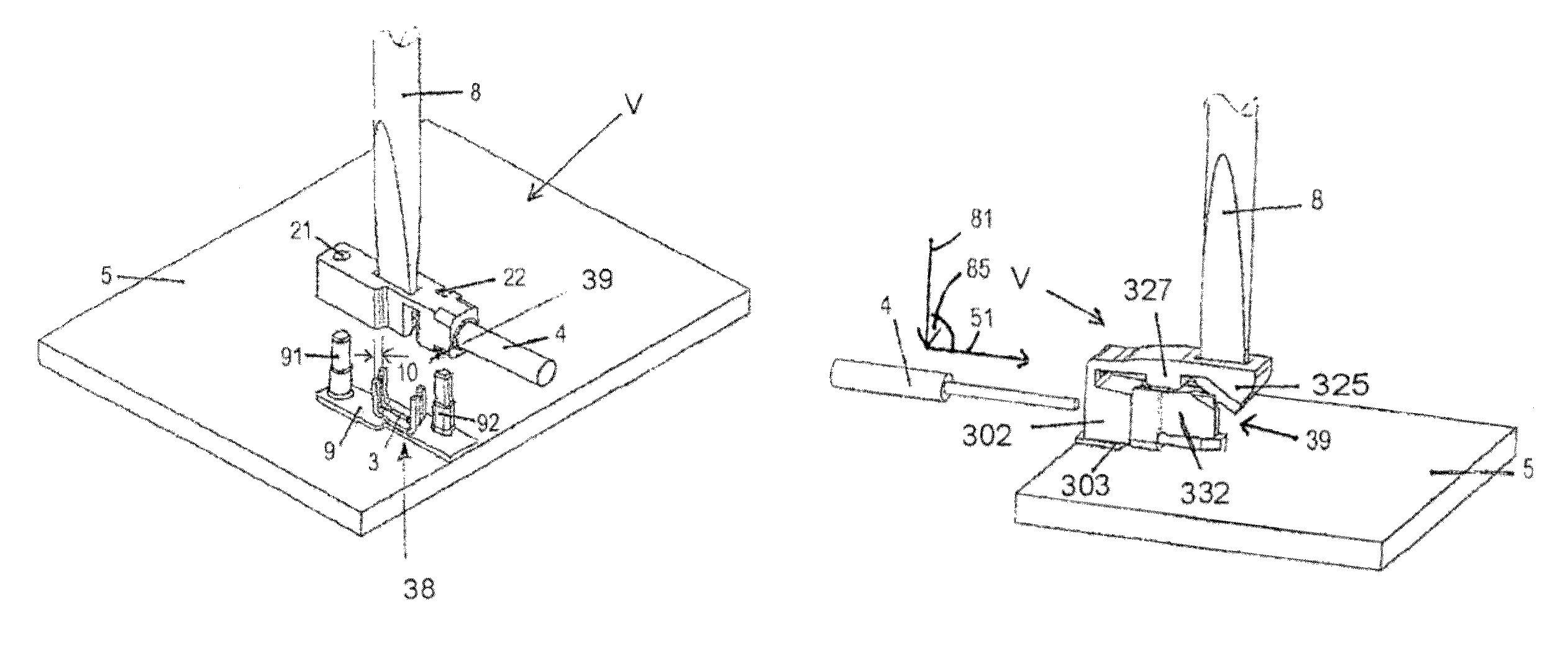
[0049]Referring now to FIGS. 3a-3d, the inventive spring terminal 1 is shown, including a housing 302 for connecting the bare end of a conductor 4 to a contact arrangement 303, mounted on a printed circuit board base 5. In the assembling shifting state V of FIGS. 3a-3c, the conductor 4 can be displaced in housing part 2 and is not clamped between clamping jaw contacts 331, 332, whereas in the clamping state K of FIG. 3d, the conductor 4 is clamped between clamping jaws 331, 332 of the contact assembly 303.

[0050]As in the embodiments of FIGS. 1 and 2, the shape of housing part 302 and the shape of contact assembly 303 are so executed in a manner corresponding to each other that it is possible to arrange housing part 302 upon contact assembly 303, in particular, with the help of contact adjusting means 325.

[0051]In the embodiment of FIGS. 3a-3d, the contact assembly includes only two clamping jaw contacts 331, 332, which essentially are arranged in V-shape with respect to each other a...

eighth embodiment

[0066]FIGS. 8a and 8b illustrate the inventive spring terminal, including a wedge-shaped adjusting means 835 arranged on the pivotable rocker arm 840 of contact assembly 803. Rocker arm 840 is pivotally connected with contact assembly 803 by means of a hinge 871 and can be swung around a pivot axis 872. Insertion opening 7 contained in the rocker arm 840 is adapted to receive the tip of the actuation tool 8, which, upon actuation, opens contact part 3.

[0067]Leaf spring contacts 831, 832, analogous to those of the embodiment of FIG. 3, are connected in a V-shaped fashion and have an open side 38 and a closed side 39, whereby in the shifting state V on the open side 38, they are spaced apart from each other, and on the closed side 39, they rest against each other.

[0068]Starting from adjoining leaf spring contacts 831, 832, in order to be able to insert adjusting means 835 between leaf springs 831, 832, the latter are bent outwardly on their sides facing the adjusting means 835.

[0069]T...


PUM


Abstract

An electrical connector for connecting the bare end of an insulated conductor with a circuit on a printed circuit board, including a horizontal printed circuit board having an electrical circuit thereon, an electrically conductive contact arrangement mounted on, and electrically connected with the circuit of, the printed circuit board, the contact arrangement including at least two spaced resilient contacts having adjacent end portions that are biased together, a housing formed from electrically insulating material and containing a conductor opening for receiving the conductor bare end; and a positioning arrangement operable by an actuating tool for positioning the conductor bare end in a clamped position between the contact end portions. When the contact arrangement is in the form of a pair of leaf spring contacts connected in a V-shaped manner, an adjusting device is provided for adjusting the space between the adjacent ends of the contacts.

Description

REFERENCE TO RELATED APPLICATIONS[0001]This application is a national stage application under 35 U.S.C. §371 of PCT International Application No. PCT / EP2010 / 070075 filed Dec. 17, 2010, claiming priority of the German application No. 20 2010 000 681.3 filed Jan. 7, 2010.BACKGROUND OF THE INVENTION[0002]1. Field of the Invention[0003]An electrical connector for connecting the bare end of an insulated conductor with a circuit on a printed circuit board, including a horizontal printed circuit board having an electrical circuit thereon, an electrically conductive contact arrangement mounted on, and electrically connected with the circuit of, the printed circuit board, the contact arrangement including at least two spaced resilient contacts having adjacent end portions that are biased together, a housing formed from electrically insulating material and containing a conductor opening for receiving the conductor bare end; and a positioning arrangement operable by an actuating tool, such as ...

Claims


Application Information

Patent Timeline
Patent Type & Authority Patents(United States)
IPC IPC(8): H01R11/20
CPCH01R4/2433H01R4/4836H01R13/193H01R4/48275H01R4/48365H01R4/48455
Inventor FEHLING, STEPHANCLASSEN, CONSTANTIN
Owner WEIDMULLER INTERFACE GMBH & CO KG
Why Eureka
Try Eureka