Vapor deposition device, vapor deposition method, and organic EL display device

a display device and vapor deposition technology, applied in vacuum evaporation coatings, electroluminescent light sources, coatings, etc., can solve the problems of difficult to achieve high definition, difficult to perform highly accurate patterning, and high so as to reduce the incidence angle reduce the effect of vapor deposition particles and reduced vapor deposition particle siz

Active Publication Date: 2014-03-18
SHARP KK
View PDF12 Cites 27 Cited by
  • Summary
  • Abstract
  • Description
  • Claims
  • Application Information

AI Technical Summary

Benefits of technology

[0029]According to the vapor deposition device and the vapor deposition method of the present invention, vapor deposition particles that have passed through mask openings formed in the vapor deposition mask are caused to adhere onto a substrate while one of the substrate and a vapor deposition unit is moved relative to the other, and therefore a vapor deposition mask that is smaller than the substrate can be used. Therefore, it is possible to form a coating film on a large-sized substrate by vapor deposition.
[0030]A plurality of limiting portions that separate a plurality of limiting openings selectively capture the vapor deposition particles entering the limiting openings according to the incidence angles thereof, and therefore only vapor deposition particles having a predetermined incidence angle or less can enter the mask openings. Accordingly, the maximum incidence angle of the vapor deposition particles with respect to the substrate is reduced, and therefore blurring that occurs at the edge of the coating film formed on the substrate can be suppressed.
[0031]The limiting unit is constituted by a plurality of plate members, and therefore only a plate member to which the vapor deposition material has adhered needs only to be replaced. In other words, it is not necessary to replace the entire limiting unit to which the vapor deposition material has adhered. Therefore, a device for replacement can be simplified, and therefore the cost in the vapor deposition device can be reduced. Also, a period of time required for replacement can be shortened, and therefore a drop in the throughput of the device resulting from the replacement can be reduced. Therefore, vapor deposition can be efficiently performed at a low cost.
[0032]An organic EL display device of the present invention includes a light emitting layer formed by using the above-described vapor deposition method, and therefore the light emitting layer in which edge blurring is suppressed can be inexpensively formed. Therefore, it is possible to provide an inexpensive organic EL display device that has excellent reliability and display quality and has a large size.

Problems solved by technology

However, when the mask is made large, a gap is likely to appear between the substrate and the mask by the mask being bent or being extended by its own weight.
For this reason, it is difficult to perform highly accurate patterning, and it is therefore difficult to achieve high definition due to the occurrence of vapor deposition positions being positionally offset and the occurrence of color mixing.
Also, when the mask is made large, the mask as well as a frame or the like for holding the mask need to be gigantic, which increases the weight and makes handling thereof difficult.
As a result, there is a possibility that productivity and safety might be compromised.
Also, the vapor deposition device and devices that are used together therewith need to be made gigantic and complex as well, which makes device designing difficult and increases the installation cost.
For the reasons described above, the conventional methods for vapor deposition by color that are described in Patent Documents 1 and 2 are difficult to adapt to large-sized substrates, and it is difficult to perform vapor deposition by color on large-sized substrates such as those having a size exceeding 60 inches on a mass manufacturing level.

Method used


Image

  • Vapor deposition device, vapor deposition method, and organic EL display device
  • Vapor deposition device, vapor deposition method, and organic EL display device
  • Vapor deposition device, vapor deposition method, and organic EL display device

Examples


embodiment 1

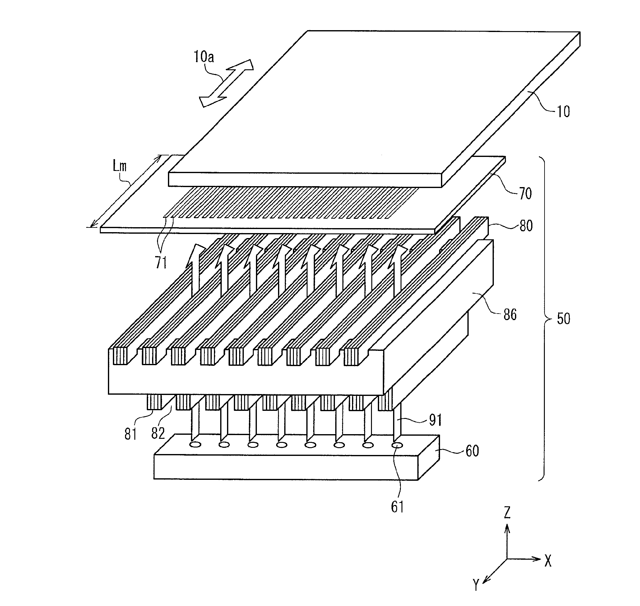
[0154]FIG. 5 is a perspective view showing the basic configuration of the vapor deposition device according to Embodiment 1 of the present invention. FIG. 6 is a front cross-sectional view of the vapor deposition device shown in FIG. 5, along a plane passing across a vapor deposition source 60.

[0155]A vapor deposition source 60, a vapor deposition mask 70, and a limiting unit 80 disposed therebetween constitute a vapor deposition unit 50. The substrate 10 moves along an arrow 10a at a constant speed with respect to the vapor deposition mask 70 on the opposite side from the vapor deposition source 60. For the sake of convenience of the description given below, an XYZ orthogonal coordinate system is set in which a horizontal axis parallel to the movement direction 10a of the substrate 10 is defined as the Y axis, a horizontal axis perpendicular to the Y axis is defined as the X axis, and a vertical axis perpendicular to the X axis and the Y axis is defined as the Z axis. The Z axis is...

embodiment 2

[0222]With Embodiment 1 described above, the plate member that is the undermost layer to which that vapor deposition material 95 has adhered is removed from the vapor deposition chamber 100, and a clean plate member other than this is stacked on the plate member that is the uppermost layer. In contrast, with Embodiment 2, in the case where the vapor deposition material 95 has adhered to only the lower surface of the plate member that is the undermost layer, the plate member is turned over and stacked on the plate member that is the uppermost layer, instead of removing the plate member from the vapor deposition chamber 100.

[0223]Hereinafter, Embodiment 2 will now be described, focusing on differences from Embodiment 1. In diagrams referenced in the following description, the same reference numerals are given to components corresponding to the components described in Embodiment 1, and redundant description thereof will be omitted.

[0224]Hereinafter, the maintenance method for the limit...

embodiment 3

[0238]In Embodiments 1 and 2 described above, all of the plurality of plate members constituting the limiting unit 80 are the same. In contrast, in Embodiment 3, each of the plurality of plate members constituting the limiting unit 80 has a different arrangement of through holes.

[0239]Hereinafter, Embodiment 3 will now be described, focusing on differences from Embodiments 1 and 2. In diagrams referenced in the following description, the same reference numerals are given to components corresponding to the components described in Embodiment 1, and redundant description thereof will be omitted.

[0240]In order to simplify description, Embodiment 3 will be described, using an example in which the limiting unit 80 is constituted by three plate members.

[0241]FIG. 14 is a partial plan view of three plate members 831, 832 and 833 constituting a limiting unit 80 of a vapor deposition device according to Embodiment 3. The plate members 831, 832 and 833 have the same external dimensions (that i...


PUM

PropertyMeasurementUnit
sizeaaaaaaaaaa
diameteraaaaaaaaaa
thicknessaaaaaaaaaa

Abstract

Vapor deposition particles (91) discharged from at least one vapor deposition source opening (61) pass through a plurality of limiting openings (82) of a limiting unit (80) and a plurality of mask openings (71) of a vapor deposition mask (70), and adhere to a substrate (10) that relatively moves along a second direction (10a) so as to form a coating film. The limiting unit includes a plurality of plate members stacked on one another. Accordingly, it is possible to efficiently form a vapor deposition coating film in which edge blurring is suppressed on a large-sized substrate at a low cost.

Description

CROSS REFERENCE TO RELATED APPLICATIONS[0001]This is a U.S. National Phase patent application of PCT / JP2012 / 055358, filed Mar. 2, 2012, which claims priority to Japanese patent application no. 2011-053078 filed Mar. 10, 2011, each of which is hereby incorporated by reference in the present disclosure in its entirety.TECHNICAL FIELD[0002]The present invention relates to a vapor deposition device and a vapor deposition method for forming a coating film having a predetermined pattern on a substrate. The present invention also relates to an organic EL (Electro Luminescence) display device including an organic EL element including a light emitting layer formed by vapor deposition.BACKGROUND ART[0003]In recent years, flat panel displays are used in various commodity products and fields, and thus flat panel displays are required to have a large size, high image quality and low power consumption.[0004]Under the circumstances, organic EL display devices, which include an organic EL element t...

Claims


Application Information

Patent Timeline
Patent Type & Authority Patents(United States)
IPC IPC(8): C23C16/00H01L21/31
CPCC23C14/243C23C14/56H05B33/10H01L51/5012C23C14/042H01L51/0011H01L51/56C23C14/564H10K71/166H10K50/11H10K71/00
Inventor SONODA, TOHRUKAWATO, SHINICHIINOUE, SATOSHIHASHIMOTO
Owner SHARP KK
Why Eureka
Try Eureka