Heat treatment apparatus

a technology of heat treatment apparatus and heating coil, which is applied in the direction of electric/magnetic/electromagnetic heating, coating, coil arrangement, etc., can solve the problems of deteriorating in-plane temperature uniformity of susceptors and/or temperature uniformity between susceptors, and affecting the efficiency of heating coils

Inactive Publication Date: 2014-03-18
TOKYO ELECTRON LTD
View PDF15 Cites 2 Cited by
  • Summary
  • Abstract
  • Description
  • Claims
  • Application Information

AI Technical Summary

Benefits of technology

[0012]Moreover, the susceptors may be made of a conductive material having a large resistivity, and the sidewall of the processing chamber may be made of a material having a resistivity smaller than that of the susceptors, so that the susceptors can be selectively inductively heated. As a consequence, it is possible to control the sidewall temperature separately from the wafer temperature by using another heating unit. In that case, even if a temperature difference occurs between the susceptors and peripheral parts thereof, the in-plane temperature uniformity of the wafers can be maintained by controlling the in-plane temperatures of the susceptors.
[0024]In accordance with the present invention, when the substrates mounted on the susceptors are heated at the same time, the susceptors are inductively heated by generating AC magnetic fields in a direction parallel to the mounting surfaces of the susceptors. Therefore, the distribution of the in-plane temperatures of the susceptors can be variable. Accordingly, it is possible to control the distribution of the in-plane temperatures of the substrates mounted on the susceptors.

Problems solved by technology

However, the method using an electric furnace is disadvantageous in that a long period of time is required to increase or decrease a wafer temperature due to large heat capacity of the entire furnace to thereby decrease productivity remarkably.
However, if the high frequency induction heating is performed in the cold wall type heat treatment apparatus having a plurality of susceptors of small heat capacity, in-plane temperature uniformity of the susceptors and / or temperature uniformity between the susceptors are deteriorated due to a difference between temperatures of the susceptors and an ambient temperature (e.g., temperatures of inner walls of the reaction tube and the like).
Furthermore, temperature uniformity between a plurality of wafers and in-plane temperature uniformity of each wafer may be deteriorated.
However, no prior art has disclosed a method for controlling temperature uniformity of each wafer, and there has not yet been known a method for controlling in-plane temperature uniformity of wafers which can be applied to a batch type heat treatment apparatus for processing a plurality of wafers simultaneously.

Method used


Image

  • Heat treatment apparatus
  • Heat treatment apparatus
  • Heat treatment apparatus

Examples


Embodiment Construction

[0037]The embodiments of the present invention will be described with reference to the accompanying drawings which form a part hereof. Throughout this specification and the drawings, like reference numerals designate like parts having substantially identical functions, and redundant description thereof will be omitted.

[0038](Configuration Example of Substrate Processing Apparatus)

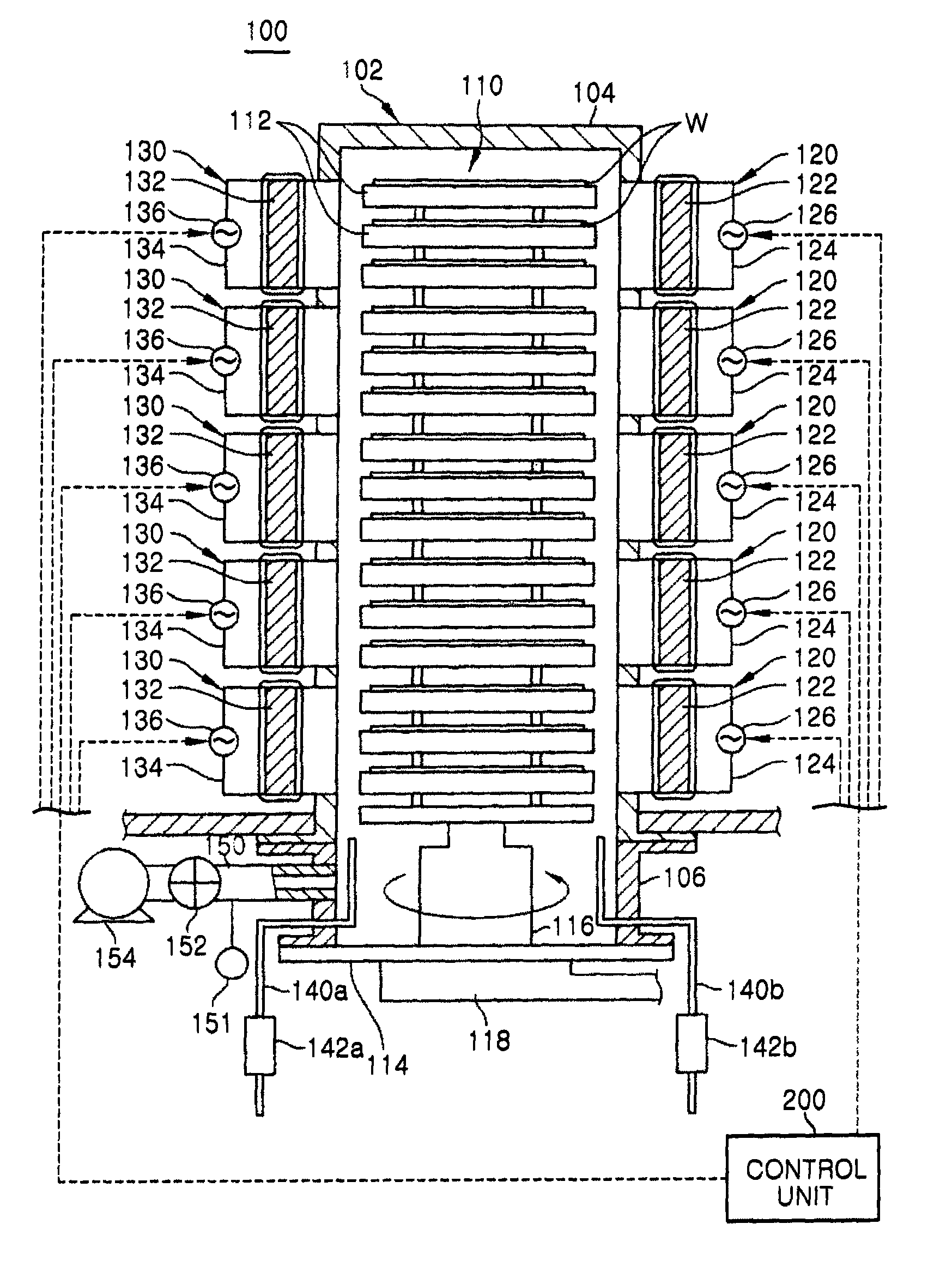
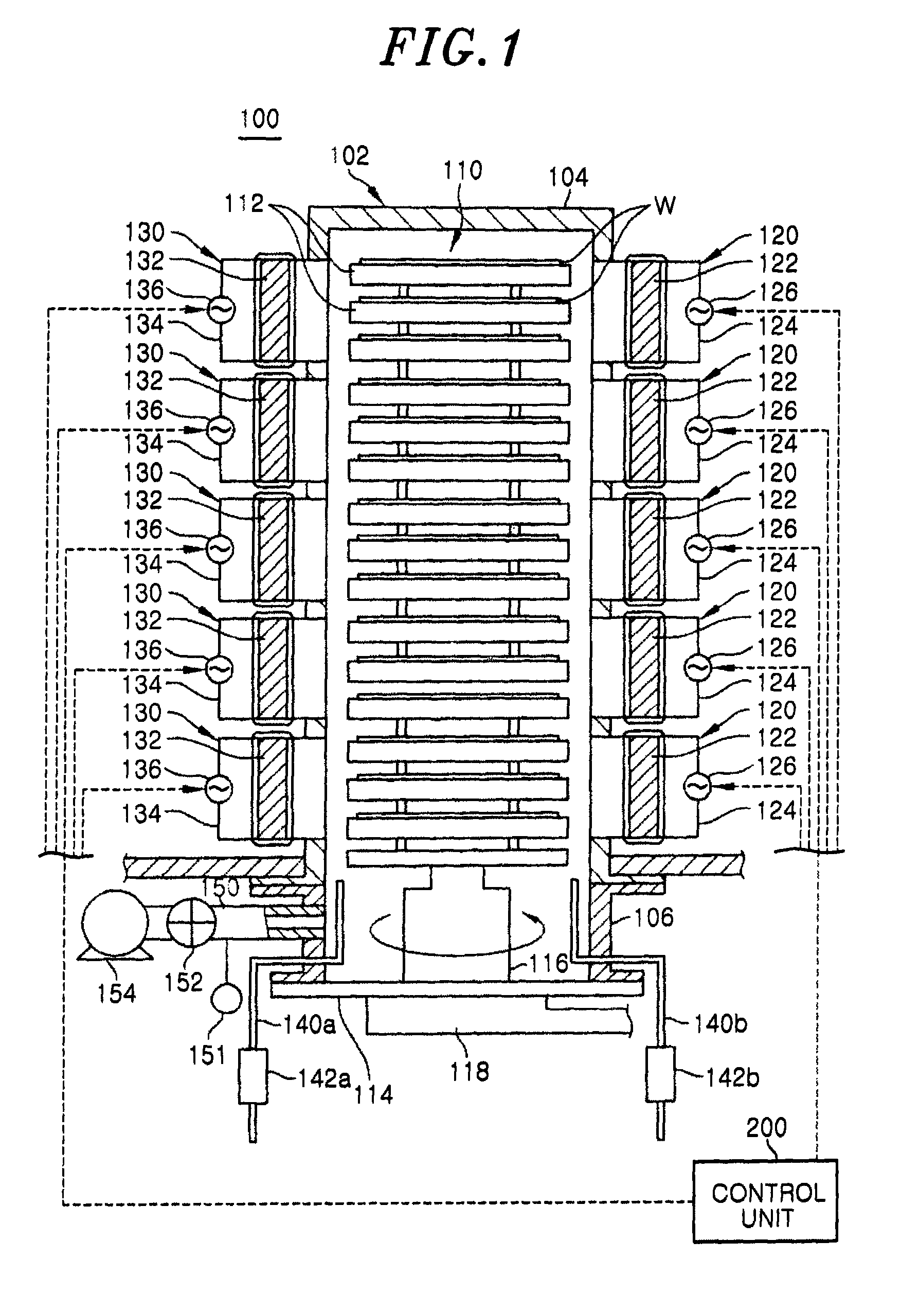
[0039]First, a substrate processing apparatus applied to a substrate processing system in accordance with an embodiment of the present invention will be described. Here, a batch type vertical heat treatment apparatus (hereinafter, simply referred to as a “heat treatment apparatus”) capable of performing a heat treatment on a plurality of target substrates to be processed, e.g., semiconductor wafers at the same time will be described as an example of a substrate processing apparatus with reference to the drawings. FIG. 1 is a cross sectional view showing a configuration example of the heat treatment apparatu...


PUM

PropertyMeasurementUnit
pressureaaaaaaaaaa
temperatureaaaaaaaaaa
pressureaaaaaaaaaa

Abstract

Provided is a heat treatment apparatus which, when simultaneously heating substrates placed on susceptors, is capable of controlling the uniformity of temperature within each substrate. The heat treatment apparatus includes: a reaction tube which performs predetermined treatment to wafers; a plurality of susceptors each of which has a mounting surface for mounting the wafer and is made of a conductive material; a rotatable quartz boat wherein the susceptors spaced apart in a direction perpendicular to the mounting surfaces are arranged and supported in the reaction tube; a magnetic field generating unit which is arranged on a sidewall of the processing chamber and includes a pair of electromagnets which generate an AC magnetic field in a direction parallel to the mounting surfaces of the susceptors and inductively heat the susceptors; and a control unit which controls the AC magnetic field generated by the magnetic field generating unit.

Description

[0001]This application is a Continuation Application of PCT International Application No. PCT / JP2009 / 060527 filed on Jun. 9, 2009, which designated the United States.FIELD OF THE INVENTION[0002]The present invention relates to a heat treatment apparatus for performing a predetermined heat treatment on a substrate, e.g., a semiconductor wafer, a glass substrate or the like.BACKGROUND OF THE INVENTION[0003]In order to manufacture a semiconductor integrated circuit, various heat treatments such as a film forming process for forming, e.g., a silicon film or a silicon oxide film, an oxidation process and the like are performed on a substrate surface. When the heat treatments are carried out, there is often used a so-called batch type heat treatment apparatus capable of simultaneously processing a plurality of semiconductor wafers (hereinafter, simply referred to as a “wafers”).[0004]The batch type heat treatment apparatus employs a method for heating a reaction tube in which a plurality ...

Claims


Application Information

Patent Timeline
Patent Type & Authority Patents(United States)
IPC IPC(8): H05B6/10C23C16/00
CPCH05B6/365H05B6/105H05B6/44C23C16/46H01L21/67109
Inventor YONENAGA, TOMIHIROKAWANO, YUMIKO
Owner TOKYO ELECTRON LTD
Why Eureka
Try Eureka