Length measuring system

a technology of measuring system and length, which is applied in the direction of measuring tape, using mechanical means, instruments, etc., can solve the problems of inability to guarantee the permanent secure positioning of the measurement element on the support structure, inability to determine and inability to ensure the accuracy of the respective length measurement or position determination

Active Publication Date: 2014-03-25
SCHNEEBERGER HLDG AG
View PDF18 Cites 0 Cited by
  • Summary
  • Abstract
  • Description
  • Claims
  • Application Information

AI Technical Summary

Benefits of technology

[0007]The present invention relates to creating a length measuring system with which the said disadvantages can be avoided and which is furthermore virtually maintenance-free.
[0011]Several advantages are achieved by the fact that the second layer is applied to a support layer consisting of a metallic material. Metallic materials have relatively high mechanical strength and relatively good resistance to wear (for example to wear by abrasion), in particular compared with plastics suitable for the production of flexible strips. Consequently, it is possible to select the thickness of the first layer to be relatively small (the first layer can for example be a thin metallic foil). Thanks to the small thickness of the first layer, it becomes possible to scan the measurement body formed in the second layer (in the form of a plurality of magnetised regions) by means of a measuring device which is suitable for detecting the magnetised regions in the second layer which form the measurement body, from the side of the first layer opposite the second layer, and in particular through the first layer, and to achieve relatively large measurement signals in the process. Thanks to the relatively high wear resistance of the metallic material, it is also possible when scanning the measurement body to bring the respective measuring device into mechanical contact with the first layer and to guide it in a touching manner along the surface of the first layer without touching the second layer and without damaging the second layer. In the process it is also ensured that the measuring device always has a distance from the second layer or from the measurement body, which is defined by the respective thickness of the first layer. If the thickness of the first layer is maintained within predefined tolerances over the entire length of the measurement element, the distance between the measuring device and the second layer or the measurement body can in this manner be controlled correspondingly precisely over the entire length of the measurement element. The latter improves the accuracy of the scanning of the measurement body by means of the respective measurement device.
[0014]The first layer can preferably consist of a wear-resistant, abrasion-resistant, hard and / or corrosion-resistant material, in particular steel or a steel alloy. This first layer acts as a wear-resistant covering or protective layer for the second layer and protects the magnetisation from subsequent change by mechanical or chemical influences.
[0015]In a development of this embodiment, it is provided for the (magnetisable) second layer to be based on galvanic deposition of an alloy layer, in particular on galvanic production of cobalt alloy-based layers. Galvanic deposition of metallic layers is in particular suitable for economical mass production at comparatively low cost and high throughput. Cobalt alloys in turn have the advantage that a particularly robust and corrosion-resistant layer can be created. Other alloy layers are of course also conceivable, with which a robust magnetisable layer can be created. In this case the first layer acts as a support layer for the second layer. A prefabricated, flexible, metallic strip can for example be used as the first layer.
[0016]In order to scan the measurement body by means of a measuring unit or sensor, the first layer of the measurement element can preferably face the measuring unit or the respective sensor. The measurement body can then be scanned through the first layer. The measuring unit or the respective sensor for scanning the measurement body can in particular be guided in a touching manner over the first layer during scanning, the measuring unit or sensor not coming into contact with the second layer or the measurement body. The measuring unit or the respective sensor of the measuring unit can in this manner be guided at a constant distance from the second layer and thus from the measurement body. This allows reliable scanning of the measurement body with a high degree of measuring accuracy. As scanning takes place without mechanical contact with the second layer, scanning is not connected with any wear at all for the second layer.
[0018]It is advantageous in particular in the case of a metallic first layer (support layer) to weld the measurement element to the support structure or to adhesively bond it thereon. A welded connection has the advantage compared to an adhesive fixing method that the connection is resistant to cooling lubricants, solvents or lubricants.

Problems solved by technology

Attachment by means of an adhesive connection is however disadvantageous in that permanent secure positioning of the measurement element on the support structure cannot be guaranteed.
Although measurement elements consisting of plastic are protected from wear by the contactless scanning, the necessary minimum distance between the measurement element and the reading head means that the accuracy of the respective length measurement or determination of position is limited, especially as the magnetised regions of the measurement element which contain length information or position information must generally have a minimum size so that they can be reliably scanned by the respective reading head from a predefined distance.
The disadvantage of these measurement strips is however that the measurement strip can become very dirty, as a result of which error-free scanning by the optical scanning unit can no longer be reliably ensured.

Method used


Image

  • Length measuring system
  • Length measuring system
  • Length measuring system

Examples


Embodiment Construction

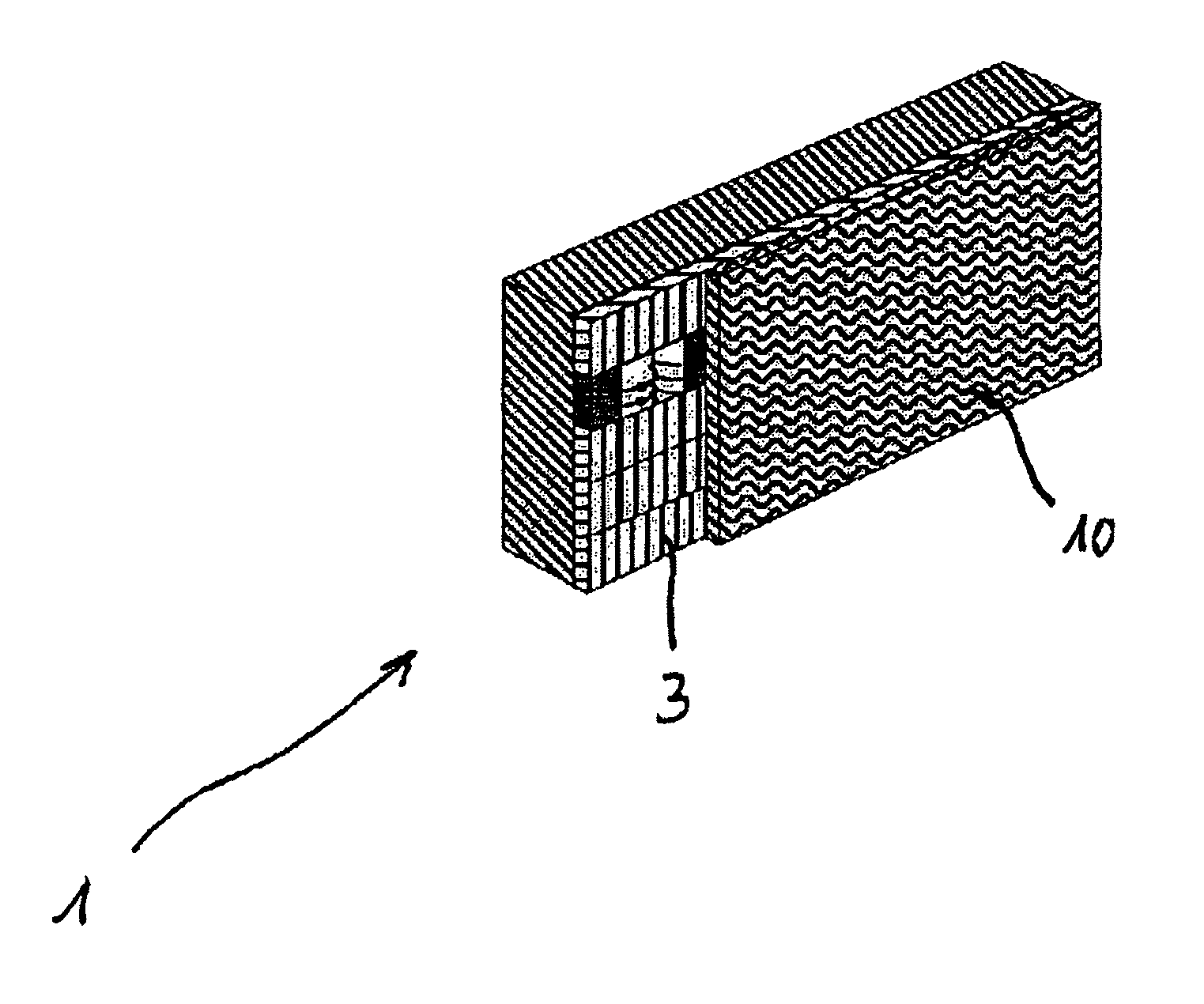
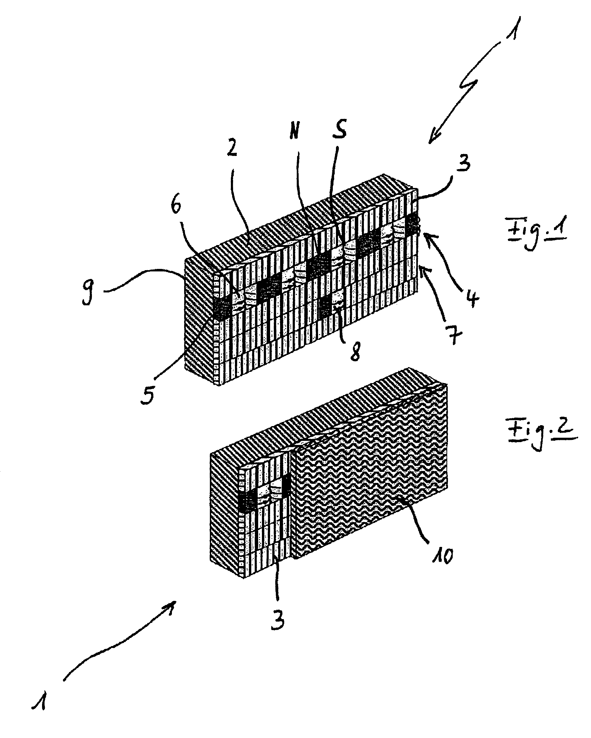
[0028]FIG. 1 shows the schematic illustration of a longitudinal section of a measurement element 1 according to an embodiment of the invention. The measurement element 1 is configured as an elastically pliable or flexible measurement strip. The measurement element 1 consists essentially of a first non-magnetic layer 2, consisting of a metallic material, and a second magnetisable layer 3.

[0029]The first (non-magnetic) layer 1 covers the second (magnetisable) layer 3 completely, at least from one side. A measurement body 4 is formed in the second layer 3 by means of a magnetic method. The measurement body 4 consists in the present example of an incremental track 5 consisting of approx. 200 μm-wide magnetised regions 6, which are arranged with alternating polarity (north and south poles) in the longitudinal direction of the measurement element 1, and a reference track 7 for determining the absolute position, the reference track 7 being provided with distance-coded markers 8. To produce...


PUM


Abstract

The invention relates to a measurement element (1, 11, 17, 26) for a length measuring system (40) in the form of a flexible strip comprising a measurement body (4) that can be scanned using a measuring unit (41) of the respective length measuring system (40). The flexible strip consists of a non-magnetic first layer (2, 13, 19, 28) and a magnetizable second layer (3, 14, 20, 29). The first layer (2, 13, 19, 28) is designed as a strip consisting of a metal material, coated at least in part on one side with the second layer (3, 14, 20, 29), said first layer acting as a support layer for the second layer. The second layer (3, 14, 20, 29) comprises several magnetizable regions that form the measurement body (4).

Description

CROSS-REFERENCE TO RELATED APPLICATIONS[0001]This application is a National Stage Application of PCT / CH2009 / 000148, filed May 8, 2009, which designates the United States and claims the priority of German Patent Application No. 20 2008 006 293.4, filed on May 8, 2008.BACKGROUND[0002]1. Field of Invention[0003]The invention relates to a length measuring system with a measurement element in the form of a flexible strip and comprises a measurement body which can be scanned with a measuring unit of the respective length measuring system.[0004]2. Related Art[0005]Strip-like measurement elements which consist of plastic and have a multiplicity of magnetisable particles which are embedded in the plastic are known from the prior art. These elongate measurement elements are generally provided with a measurement body which can for example comprise a length code or a sequence of equidistant position markings. The measurement body is generally produced by magnetising individual regions of the re...

Claims


Application Information

Patent Timeline
Patent Type & Authority Patents(United States)
IPC IPC(8): G01B7/02
CPCG01D5/145G01B3/10G01B3/004
Inventor GOETZ, KLAUS-DIETER
Owner SCHNEEBERGER HLDG AG
Why Eureka
Try Eureka