Optical data transmission system

a technology of optical data transmission and optical cable, which is applied in the direction of optical elements, multiplex communication, instruments, etc., can solve the problems of limiting the downsizing and weight reduction of optical cable, increasing the probability of failure, and a large amount of wiring and wiring work, so as to facilitate installation and replacement of the system, reduce the and reduce the effect of total length of optical cabl

Active Publication Date: 2014-03-25
PANASONIC CORP
View PDF6 Cites 1 Cited by
  • Summary
  • Abstract
  • Description
  • Claims
  • Application Information

AI Technical Summary

Benefits of technology

[0009]Herewith, the first optical splitter, small-size and lightweight and requiring no power supply wiring, can be placed at a desired position that does not block passengers in a sheet arrangement of a flight vehicle. This enables constructing an optical data transmission system with a high degree of flexibility. Furthermore, with a first optical splitter being placed in association with a seat group, a seat group including N sets of seats, N units of terminals, and a first optical splitter are delivered in one set from a seat vendor, which facilitates installation and replacement of the system. Further, with optical cables being connected between the head end and the first optical splitter and between the first optical splitter and the N units of terminals, the entire path from the head end to the terminals is implemented with optical cables and the first optical splitter unifies N pieces of optical cables, which minimizes the total wiring length of optical cables. This enables compressing the component cost of optical cables while reducing electromagnetic interference (EMI) and the weight of the aircraft body, which compresses the system cost and fuel cost.

Problems solved by technology

According to the technique disclosed in the above conventional example, however, the switch needs a power supply, and the switch itself has a complicated structure, limiting its downsizing and weight reduction.
Conventionally, a server / switch unit and a passenger-seat transceiver are connected to each other one to one, causing a huge amount of wiring and a large amount of work for wiring.
Further, the large amount of wiring increases the probability of failures (e.g. a break).
Hence, a flight vehicle cannot be equipped with an IFE system freely.

Method used


Image

  • Optical data transmission system
  • Optical data transmission system
  • Optical data transmission system

Examples


Embodiment Construction

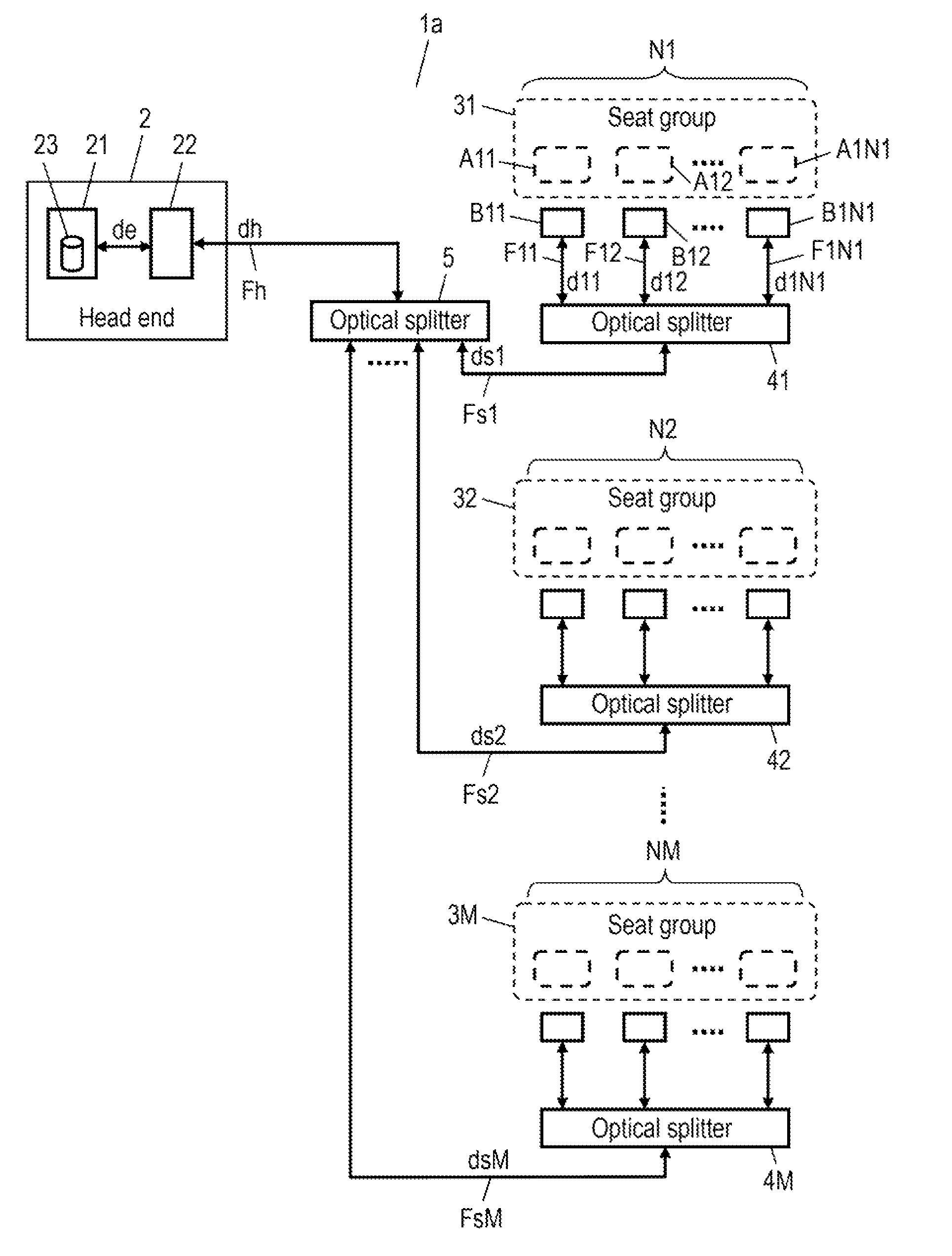
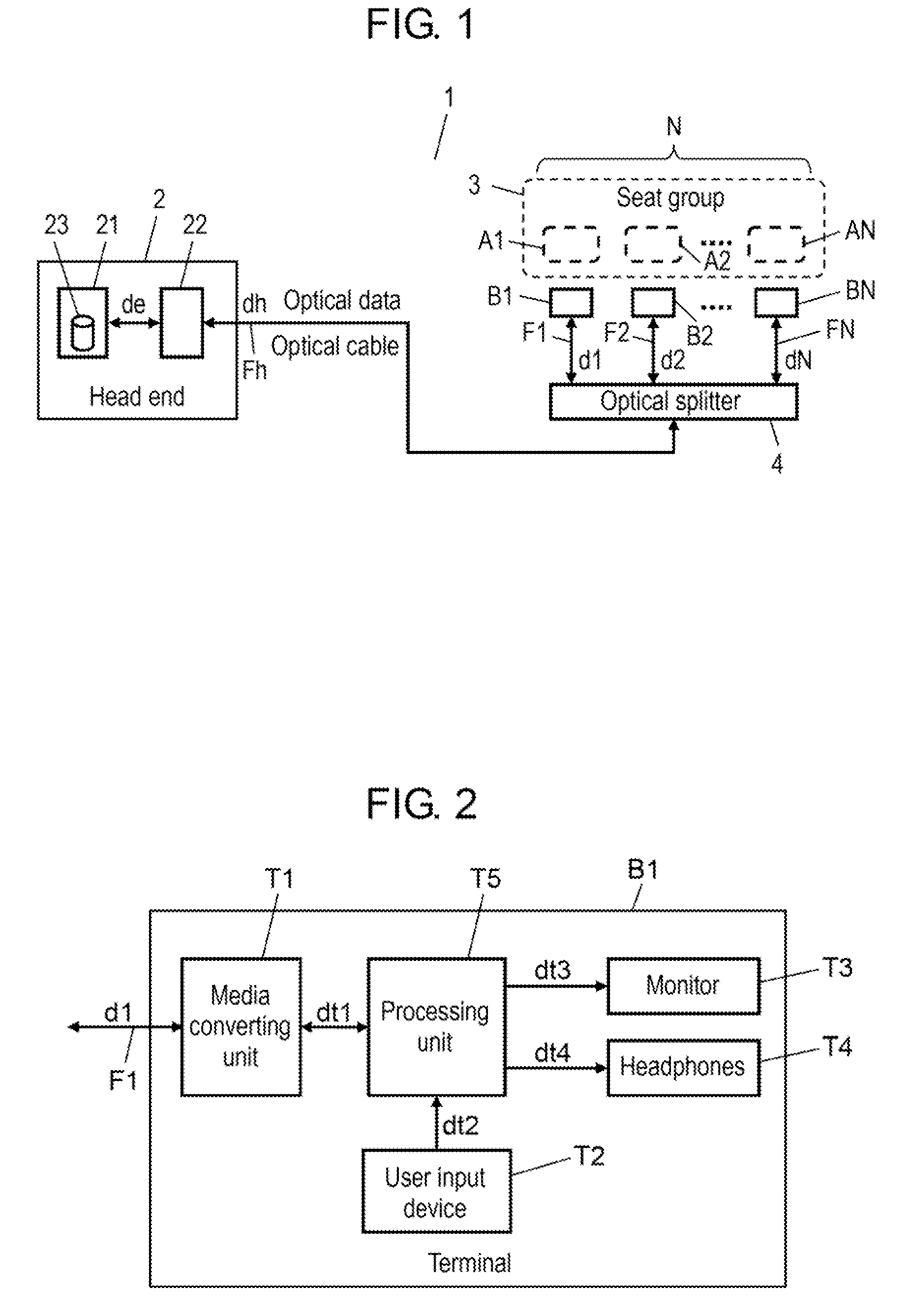
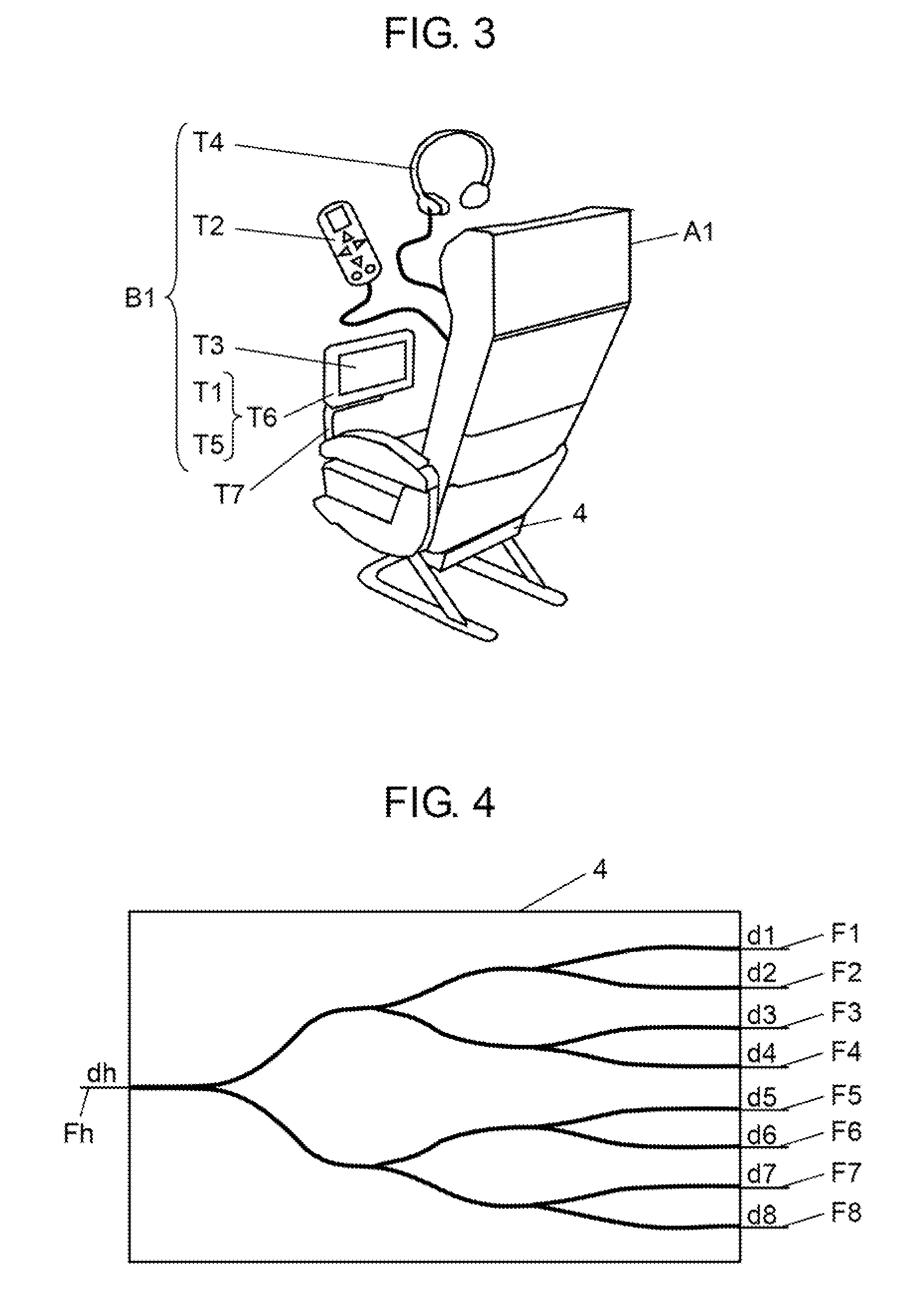
[0024]Hereinafter, a description is made of some examples of an embodiment of the present invention with reference to the related drawings. In the drawings, a component with substantially the same configuration, action, and advantages is given the same reference mark. For example, the sequence (A1, A2, . . . , An) represents a group of reference marks whose suffix increments by one and is also described as (A1 to An). A mark in a drawing is used in an expression as a variable value representing the magnitude of a signal indicated by the mark.

(1) Optical Data Transmission System 1

[0025]FIG. 1 is a block diagram showing a configuration example of optical data transmission system 1. System 1 is for transmitting optical data in a flight vehicle and includes head end 2; optical splitter 4 (first optical splitter); N (N is an integer larger than 1) pieces of terminals B1, B2, . . . , BN; plural pieces of optical cables Fh, F1, F2, . . . , FN; and seat group 3. Here, a description is made ...


PUM


Abstract

An optical data transmission system for transmitting optical data in a flight vehicle, including a head end, optical splitter, N units of terminals that process optical data received from the optical splitter to display such as video, plural optical cables connected between the head end and the optical splitter and between the optical splitter and the terminals, and a seat group including N sets of passenger seats that transmit two-way optical data and are placed close to one another. The N units of terminals are placed in association with the respective N sets of seats. The optical splitter is placed in association with the seat group; sends optical data from the head end to the N units of terminals; and reversely unifies N-series optical data, different from one another, from the N units of terminals into one series and sends it to the head end.

Description

BACKGROUND OF THE INVENTION[0001]1. Field of the Invention[0002]The present invention relates to a technique for an optical data transmission system, more particularly to that used inside an aircraft.[0003]2. Background Art[0004]In recent years, in-flight entertainment (IFE) systems have been introduced into aircrafts, allowing long-time travelers to enjoy comfortable travel owing to such as a movie, audio program, game, and Internet browsing service. Content data such as video, audio, and Internet data is usually stored in a server inside the aircraft and from there the data is sent to terminals through communication cables or wireless links. A terminal is usually placed at every passenger seat and composed of such as a unit for processing received information data, small-size video monitor, earphones, and controller.[0005]As a conventional example related to this technical field, patent literature 1 discloses an IFE system including a server / switch unit, plural video display units...

Claims


Application Information

Patent Timeline
Patent Type & Authority Patents(United States)
IPC IPC(8): H04B10/00H04J14/00H04B10/27H04B10/272
CPCH04B10/278H04B10/272
Inventor HIGASHIDA, MASAAKIOHYAMA, SATOSHI
Owner PANASONIC CORP
Why Eureka
Try Eureka