Electrical motor having radially offset cooling stream and cooling method

a technology of radial offset cooling and electric motor, which is applied in the direction of dynamo-electric machines, magnetic circuit rotating parts, magnetic circuit shapes/forms/construction, etc., can solve the problems of complex protection of magnets against displacement or corrosion by encapsulation, and only non-uniform cooling of the rotor, so as to achieve low loss in the rotor and produce more easily. , the effect of powerful cooling

Active Publication Date: 2014-04-01
FLENDER GMBH
View PDF23 Cites 12 Cited by
  • Summary
  • Abstract
  • Description
  • Claims
  • Application Information

AI Technical Summary

Benefits of technology

[0012]In particular, it is expedient for the first cooling ducts to be arranged at a lower radial level in the rotor than the second cooling ducts. In this case, the first cooling stream flows initially in the vicinity of the shaft, where it absorbs only little heat. After a certain axial distance, the first cooling stream, in the “unused” state, can provide a powerful cooling effect when it is deflected into the second cooling ducts.
[0013]The rotor can be excited by permanent magnets. These lead only to relatively low losses in the rotor, and therefore it is sufficient to divide the rotor into two core elements and to provide only one single cooling air slot in the center of the rotor. As a result, a rotor with permanent magnet excitation can be produced more easily. Otherwise, when the rotor is fitted with short-circuiting bars, a plurality of core elements can also be provided, it also being possible for the cooling stream to be routed through more than two different planes in the rotor.
[0014]Furthermore, a core element (which contains the first cooling ducts) can be offset in the circumferential direction relative to a core element which contains the second cooling ducts. This serves to reduce the torque ripple of the rotor and can be readily realized by a plurality of disks of the spacer since the offset generally has to be only very low. Therefore, the function of the spacer, specifically that of radial redirection, is likewise not adversely affected by the offset.

Problems solved by technology

In addition, the rotor is only non-uniformly cooled when the stream of cooling agent floods in.
Although more uniform cooling was achieved in this case, it is very complicated to protect the magnets against displacement or against corrosion by encapsulation.

Method used


Image

  • Electrical motor having radially offset cooling stream and cooling method
  • Electrical motor having radially offset cooling stream and cooling method
  • Electrical motor having radially offset cooling stream and cooling method

Examples


Embodiment Construction

[0021]The exemplary embodiments described in greater detail below are preferred embodiments of the present invention.

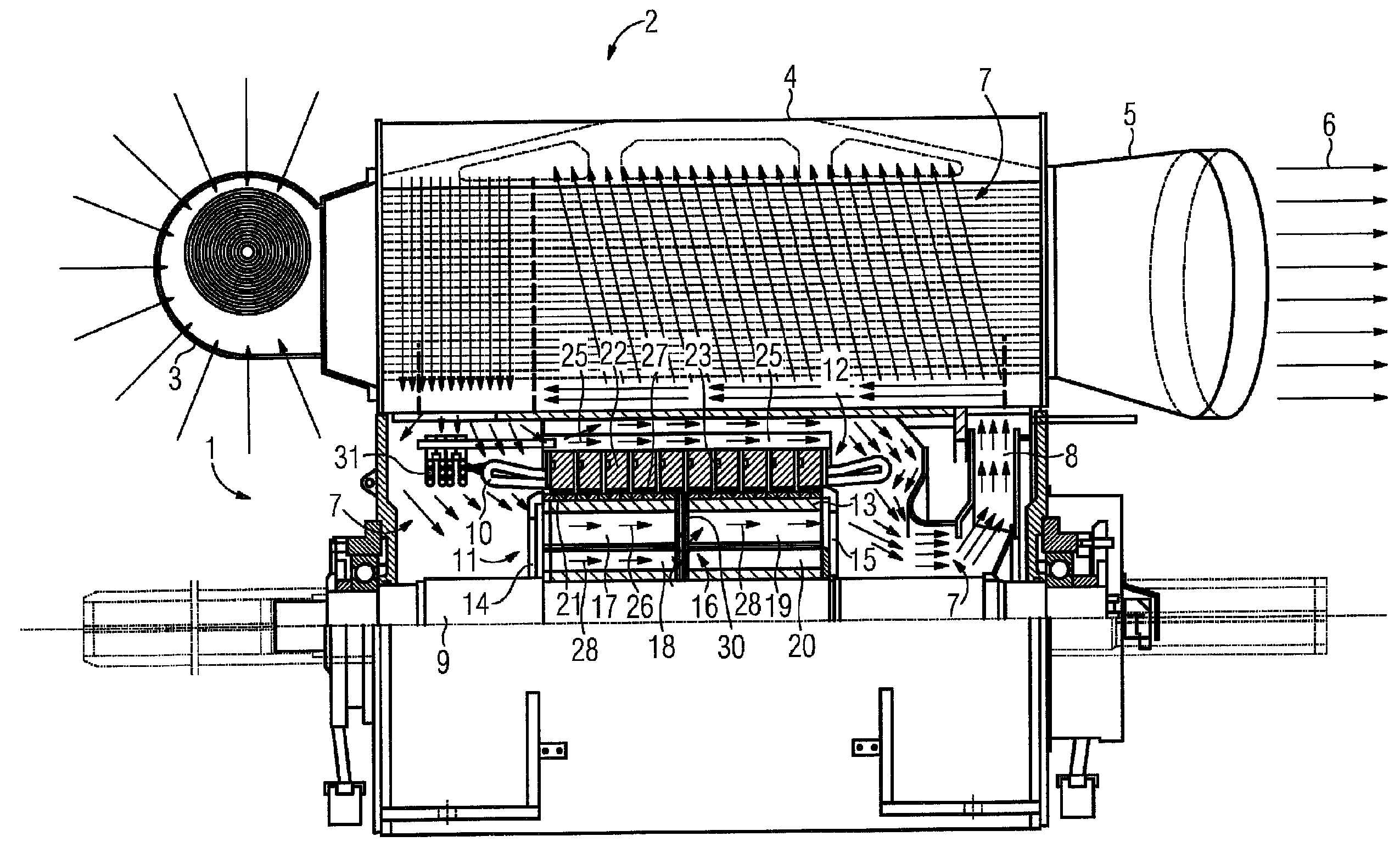
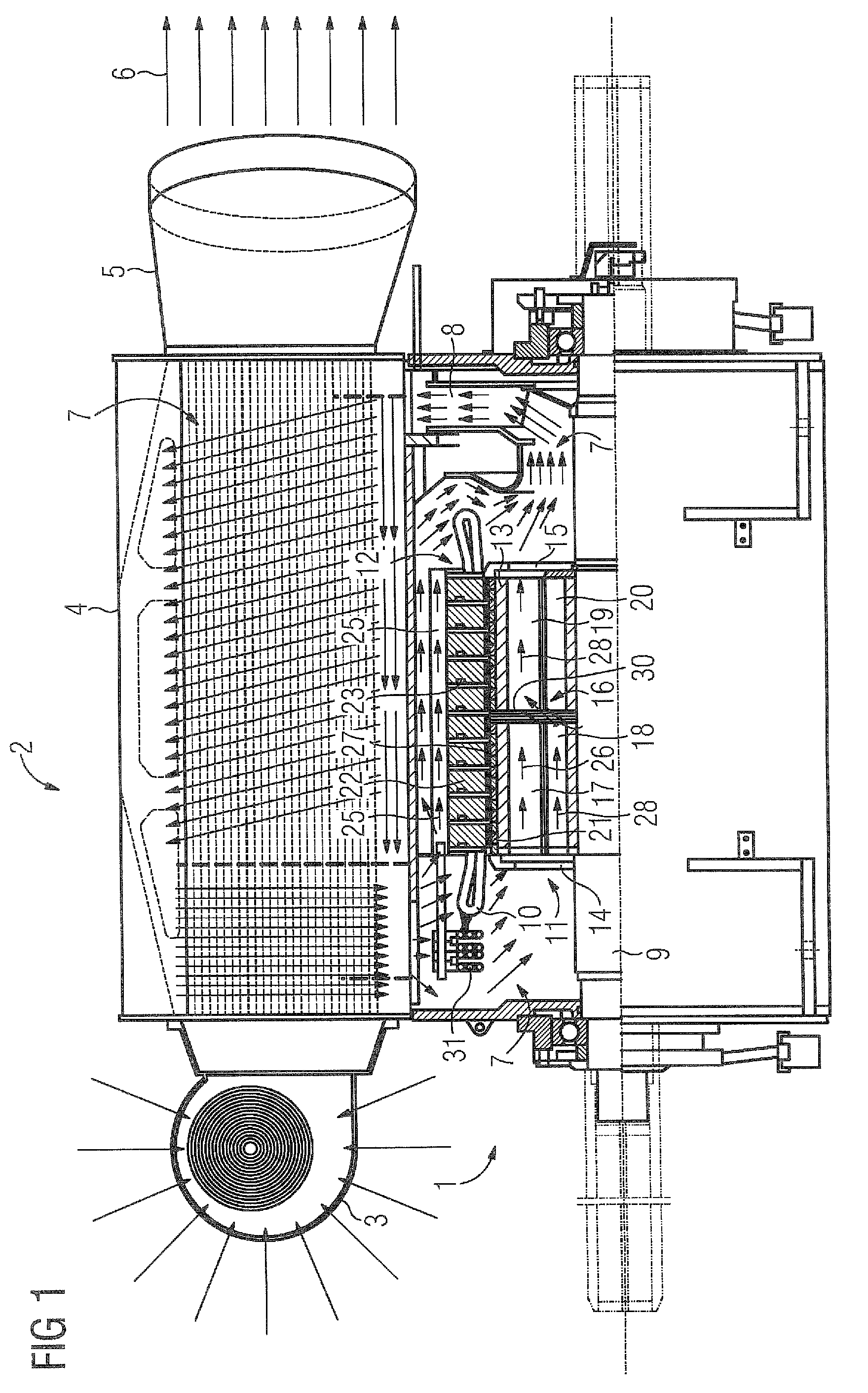
[0022]FIG. 1 shows a generator 1 having a cooling device 2. The cooling device 2 has a fan 3 for drawing in cooling air which it blows into a heat exchanger 4. The air flows from there to the outside through an outlet nozzle 5. This defines an external cooling circuit.

[0023]The heat exchanger 4 cools an internal, closed cooling circuit 7 using the external cooling circuit 6. The internal cooling circuit 7 is driven by a shaft-mounted fan 8 which is mounted on the B-side of the shaft 9 of the generator 1. The internal cooling circuit flows through the heat exchanger starting from the fan 8 and enters the winding overhang space on the A-side (drive side) of the generator. Here, said internal cooling circuit flows around the winding overhang 10 and the winding circuit 31 and then flows through the rotor 11 and the stator 12, as will be explained in greater detail below. ...


PUM


Abstract

The rotor of an electrical motor should be designed simply and able to be efficiently cooled. To this end, the invention relates to an electrical motor having a rotor that has at least one radial cooling slot (16) and axially running cooling channels. The first cooling channels (18) run having their central axis at a different radial height opposite the axis of the rotor (11) than the second cooling channels (19). A spacer (29) is arranged in the at least one radial cooling slot (16) by means of which a first cooling stream (28) can be conducted from one of the first cooling channels (18) into one of the second cooling channels (19). A second partial package (T2) in the flow direction can also be supplied with cool air in this way if it flows through the first partial package (T1) in a cool region, such as near the shaft.

Description

CROSS-REFERENCES TO RELATED APPLICATIONS[0001]This application is the U.S. National Stage of International Application No. PCT / EP2009 / 065717, filed Nov. 24, 2009, which designated the United States and has been published as International Publication No. WO 2010 / 072496 A2 and which claims the priority of German Patent Application, Serial No. 10 2008 064 498.6, filed Dec. 23, 2008, pursuant to 35 U.S.C. 119(a)-(d).BACKGROUND OF THE INVENTION[0002]The present invention relates to an electrical machine having a rotor which has at least one radial cooling slot and axially running cooling ducts which issue into the at least one radial cooling slot in said rotor. The present invention also relates to a method for cooling an electrical machine having a rotor by cooling the rotor with a cooling stream which is introduced axially into the rotor.[0003]In principle, it is necessary to supply uniformly cool air (or cooling agent) to the rotor of an electrical machine. At the same time, it should...

Claims


Application Information

Patent Timeline
Patent Type & Authority Patents(United States)
IPC IPC(8): H02K9/00
CPCH02K1/32H02K9/18
Inventor ELENDER, GUNTHERMEMMINGER, OLIVERSCHONBAUER, NORBERTSENNINGER, KARL
Owner FLENDER GMBH
Why Eureka
Try Eureka