Helmholtz resonator for a gas turbine combustion chamber

a gas turbine and resonator technology, applied in the field of resonators, can solve the problems of high cost, high number of parts and high number of parts, and the system is prone to the combustion dynamics, and achieve the effect of amplifying the deformation effect of deformable elements

Inactive Publication Date: 2014-04-08
SIEMENS AG
View PDF19 Cites 4 Cited by
  • Summary
  • Abstract
  • Description
  • Claims
  • Application Information

AI Technical Summary

Benefits of technology

[0047]At a first temperature, the spiral may expand, so that the windings reduce the distance between each other and the spiral respectively the outer wall of the spiral is pressed against the inner surface of the neck section. Thus, because the contacting windings may form an offset from the inner surface of the neck section, the effective diameter, which may be defined from the winding closest to the centre of the neck section, may decrease and the effective cross-sectional area of the neck section decreases as well.
[0048]At a second temperature, the windings of the spiral may increase the distance between each other. Thereby, the effective diameter may be defined by the inner surface of the neck section, so that the effective diameter is larger than the effective diameter adjusted with the first temperature.
[0056]According to a further exemplary embodiment, the deformable element is installed to the neck section in such a way that the length of the neck section depends on the respective gas turbine temperature (e.g. temperature of the turbine wall or the gas temperature of the gas stream). By the present exemplary embodiment, a part of the neck section, in particular a part of the wall of the neck section for instance, may be formed by the deformable element or at least parts of it, so that an expansion and reduction of deformable element may change the length and such provides a frequency adjustment of the resonator.
[0057]According to a further exemplary embodiment, the deformable element is installed to the neck section in such a way that the volume of the neck section depends on the respective gas turbine temperature (e.g. temperature of the turbine wall or the gas temperature of the gas stream). By the present exemplary embodiment, the deformable element may change its volume or its position or expanse and thus the volume of the neck section due to a change of temperature. Thus, the volume of the neck station may be provided in order to adjust the frequency. Besides, strictly speaking the actual volume may stay unmodified, but the deformable element may create a blockage for the fluid so that effectively the volume does not change but the mobility of the gas through the neck section is influenced.
[0059]According to a further exemplary embodiment, the resonator further comprises a cooling hole, wherein the cooling hole is adapted for coupling the volume of the resonator to a cooling fluid stream. The cooling hole(s) may provide a connection to a cooling system, so that for example cooling fluid may stream inside the volume (the neck section or chamber) for cooling the resonator walls. Moreover, by the cooling holes, the cooling fluid may cool the gas stream, so that the gas stream temperature may be kept constant, for instance. Thus, by the cooling holes and by the cooling fluid, an adjusting effect for adjusting the deformation of the deformable element may be provided, because the gas stream temperature inside the resonator may be adjusted. This may become important if the resonator is placed in the flame region (with high wall temperatures) inside the gas turbine, then the resonator has to be cooled and therefore the gas stream temperature within the neck may be relatively constant.

Problems solved by technology

However, these systems are prone to combustion dynamics as they run in a lean regime due to the use of the lean mixture of air and fuel.
Hence, combustion dynamics may arise as a result of flame excitation, aerodynamic induced excitation or insufficient damping.
When the load of the gas turbine is altered, in particular for example between 50% and 75%, the combustion system might be prone to the combustion dynamics.
For this approach, a high number of parts and costs are necessary.
Moreover, the use of a plurality of Helmholtz resonators might not always be appreciable due to geometrical constraints of the gas turbine.

Method used


Image

  • Helmholtz resonator for a gas turbine combustion chamber
  • Helmholtz resonator for a gas turbine combustion chamber
  • Helmholtz resonator for a gas turbine combustion chamber

Examples


Embodiment Construction

[0070]The illustrations in the drawings are schematic. It is noted that in different figures similar or identical elements are provided with the same reference signs.

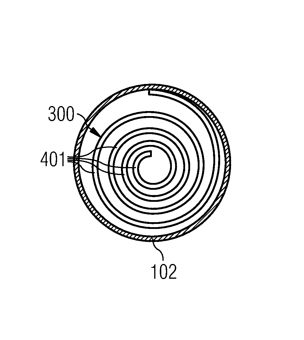
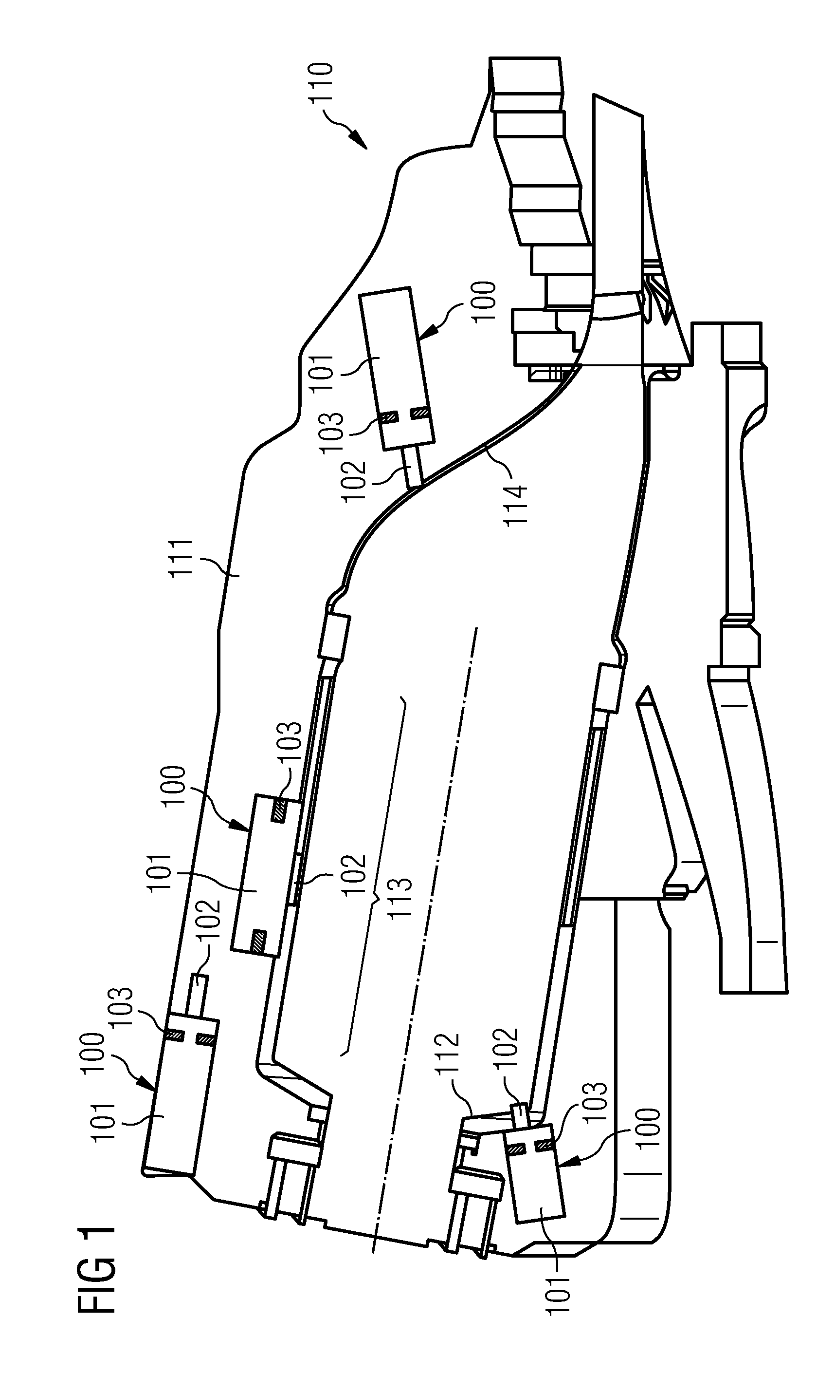
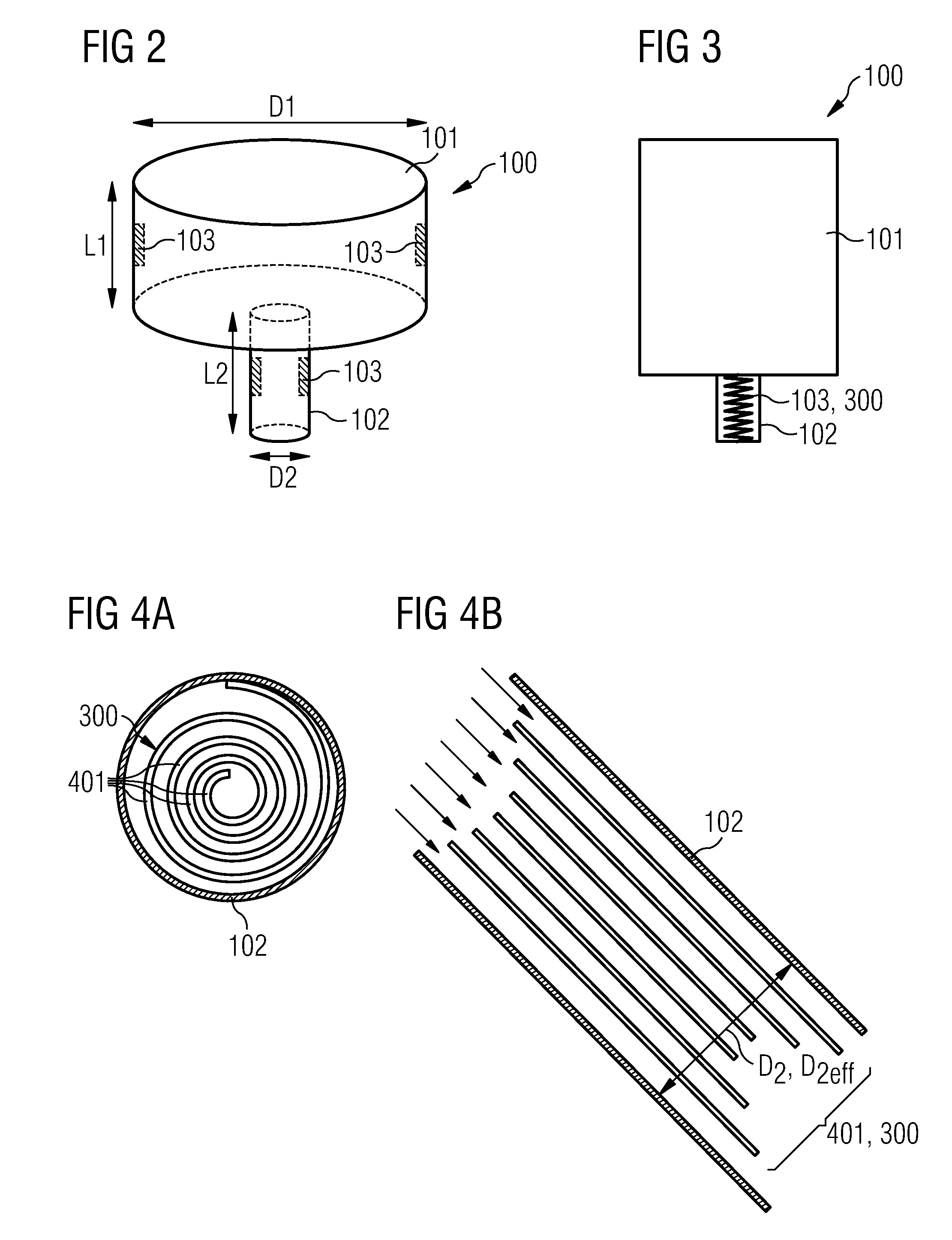
[0071]FIG. 1 shows a resonator 100 with an adaptable resonator frequency f for absorbing sound and / or pulsation or combustion dynamics generated by a gas stream of a gas turbine 110. The resonator 100 comprises a neck section 102, a chamber 101 and a deformable element 103 being deformable under influence of a change of a gas turbine temperature (e.g. temperature of turbine wall 601 (see FIG. 6) or gas temperature of the gas stream T) of the gas stream. The shape of the deformable element 103 is predetermined with respect to a respective gas turbine temperature. The neck section 102 and the chamber 101 form a volume V of the resonator 100. The neck section 102 forms a passage coupling the volume V with the gas turbine 110. The deformable element 103 is thermally coupled to the gas stream in such a way that the shape of ...


PUM


Abstract

A resonator is provided, having an adaptable resonator frequency for absorbing sound generated by a gas stream of a gas turbine. The resonator includes a neck section, a chamber and a deformable element being deformable under influence of a change of a gas turbine temperature of the gas stream. The shape of the deformable element is predetermined with respect to a respective gas turbine temperature. The neck section and the chamber form a volume of the resonator. The neck section forms a passage coupling the volume with the gas turbine. The deformable element is thermally coupled to the gas turbine in such a way that the shape of the deformable element depends on the respective gas turbine temperature. The deformable element forms a spiral and is installed to the neck section in such a way that an effective diameter of the neck section depends on the gas turbine temperature.

Description

CROSS REFERENCE TO RELATED APPLICATIONS[0001]This application is the US National Stage of International Application No. PCT / EP2010 / 063487, filed Sep. 14, 2010 and claims the benefit thereof. The International Application claims the benefits of European application No. 09012116.1 filed Sep. 23, 2009. All of the applications are incorporated by reference herein in their entirety.FIELD OF INVENTION[0002]The present invention relates to a resonator with an adaptable resonator frequency for absorbing sound or combustion dynamics peaks generated by a gas stream of a gas turbine. Furthermore, the present invention relates to a gas turbine comprising at least one resonator. Moreover, the present invention relates to a method of producing a resonator with an adaptable resonator frequency for absorbing sound generated by a gas stream of a gas turbine.ART BACKGROUND[0003]In today's gas turbines it is an aim to burn the fuel in the combustion chamber in a lean mixture of air and fuel. Such kind...

Claims


Application Information

Patent Timeline
Patent Type & Authority Patents(United States)
IPC IPC(8): F02K1/82F02C7/24F02K1/00F01N1/12
CPCF23R2900/00014F23M99/005F23R3/00F01N1/023F23M20/005
Inventor BULAT, GHENADIE
Owner SIEMENS AG
Why Eureka
Try Eureka