
Support plate and method for producing such a support plate

Active Publication Date: 2014-04-15
INFINEX HLDG
View PDF14 Cites 15 Cited by
  • Summary
  • Abstract
  • Description
  • Claims
  • Application Information

AI Technical Summary

Benefits of technology

The invention provides a support plate made of foil-like plastic material that can be used in construction and is easy to fabricate and install. The support plate reduces tension differences between the ground and the surface lining and provides enhanced decoupling. The method of producing the support plate involves applying an adhesion-strengthening layer made of a web-like material to the recessed side of the foil-like plate. This adhesion-strengthening layer closely fits the wall portions of the recess, improving its surface roughness and facilitating the application of a mortar or adhesive layer. The invention allows for a simplified process of forming the recess and lining it with the adhesion-strengthening layer simultaneously, thereby enhancing efficiency and production rates.

Problems solved by technology

Owing to varying degrees of thermal expansion between the surface lining and the ground and to the tensions associated with this, cracks may occur in the surface lining, which may ultimately lead to a detaching of parts of the surface lining.
This support plate has the disadvantage of being limited to one direction of expansibility and / or compressibility, which is a cross-direction with respect to the longitudinal extension of the dovetailed grooves.
A support plate of this type is often not capable of ensuring the necessary tension reduction.
In addition, the chambers have undercuts so that the adhesive or mortar stilts introduced into the chambers become caught in the undercuts of the chambers.
This configuration has the disadvantage that in the region of the undercut, the mortar stilts have a narrowing as compared to their post surface within the bottom of the chamber and that in the region of the narrowing, crack formation is an issue and the upstanding post members inserted into the chambers may become detached from the mortar layer resting on top of them.
The tight bond no longer exists and the tension reduction between the ground and the surface lining is no longer possible.

Method used


Image

  • Support plate and method for producing such a support plate
  • Support plate and method for producing such a support plate

Examples


Embodiment Construction

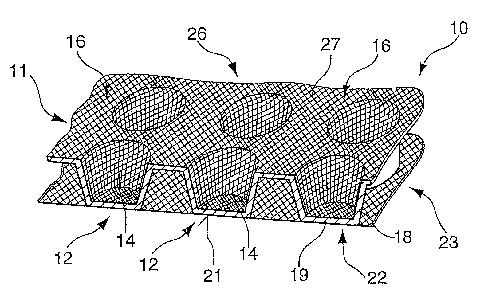
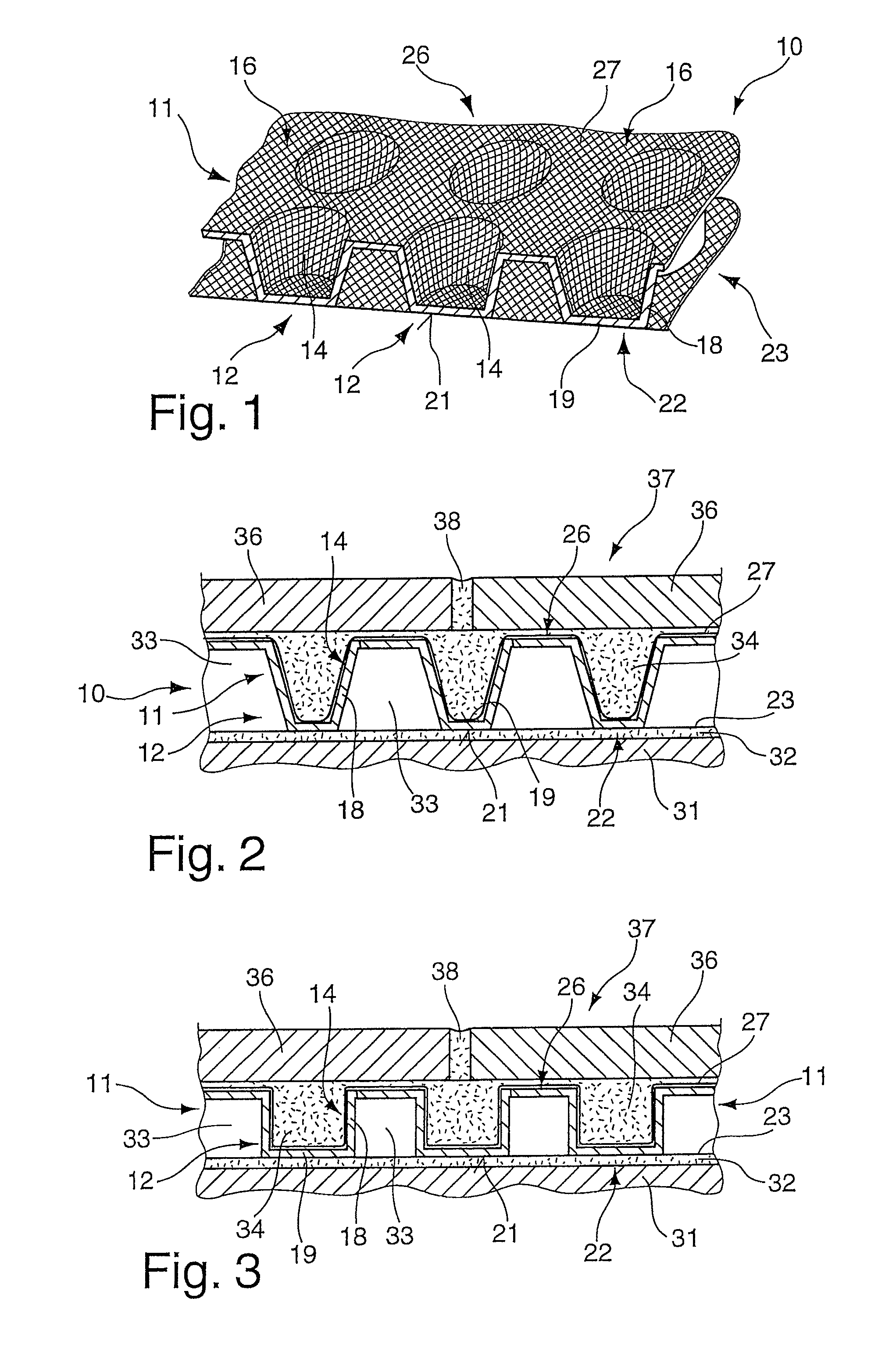
[0027]A support plate 10 according to the present invention is represented in FIG. 1. This support plate 10 comprises a foil-like plate 11 made of plastic material and having a plurality of chambers 12 constituted by means of recesses 14 formed in the foil-like plate 11. The recesses 14 of the chambers 12, preferably aligned on one side and identically oriented, are preferably realised in a repetitive arrangement of rows and columns or in some other defined pattern with respect to one another. Surface portions 16 are formed between the recesses 14 so as to connect the chambers 12 with each other. According to a first embodiment, conically tapered wall portions 18 extend from these surface portions 16 and merge each with a bottom 19, the respective outer end faces 21 of which form a first plate side 22. A woven or non-woven fabric 23 is laminated, or welded, on the end faces 21 of the chambers 12 and serves for ensuring a tight mechanical bonding between the support plate 10 and a co...


PUM

PropertyMeasurementUnit
Adhesion strengthaaaaaaaaaa
Thermoplasticityaaaaaaaaaa

Abstract

A support plate for a slab-lined wall, ceiling, or floor construction for achieving decoupling between a ground and a surface lining to be affixed to the support plate. The support plate comprises a foil-like plate made of plastic material and provided with a plurality of chambers constituted by recesses with respect to a plane of the foil-like plate, outer end faces which form a first plate side and on an opposite side a second plate side, the recesses being configured for receiving a hardening contact means for providing a contact layer for the surface lining to be applied, a woven or non-woven fabric disposed on the first plate side, and an adhesion-strengthening layer made of a web-like material being applied to at least one of the first or second plate sides for lining at least the recesses of the chambers.

Description

RELATED APPLICATIONS[0001]This application claims priority to German Application No. 10 2010 013 305.1 filed on Mar. 29, 2010, which is hereby incorporated by reference.FIELD OF INVENTION[0002]The invention relates to a method of producing a support plate and to a support plate for a slab-lined floor, wall, or ceiling construction for achieving decoupling between the ground and the surface lining to be applied to the foil-like plate.BACKGROUND[0003]In many cases, slab coverings are laid using what is called a thin-bed method, with an appropriate contact adhesive being utilised in order to affix the slab coverings to the ground. Owing to varying degrees of thermal expansion between the surface lining and the ground and to the tensions associated with this, cracks may occur in the surface lining, which may ultimately lead to a detaching of parts of the surface lining.[0004]In order to reduce such tension differences, DE 37 0441 4 A1 proposes a support plate made of a foil-like plastic...

Claims


Application Information

Patent Timeline
IPC IPC(8): E04F15/02
CPCE04F15/18E04F13/04E04F15/182E04F15/185E04F15/186Y10T156/1028Y10T156/103
Inventor HARTL, MARTIN
Owner INFINEX HLDG
Learn More