Coordinate measuring machine

a technology of coordinate measuring machine and measuring machine, which is applied in the direction of transmission, electrical/magnetic measuring arrangement, using electrical/magnetic means, etc., can solve the problems of limited system work parameters, large space requirements, and a lot of time for developing programs in automated measurement conditions, so as to achieve better dynamic management and simplify and more compact

Active Publication Date: 2014-04-22
TESA SE
View PDF10 Cites 7 Cited by
  • Summary
  • Abstract
  • Description
  • Claims
  • Application Information

AI Technical Summary

Benefits of technology

[0008]One aim of the present invention is to propose a measuring machine that is simpler and more compact than the known devices. The invention also enables the needs of the CMM as compared with the well-known CNC to be served by affording a better dynamic management of the regulation process of known devices.

Problems solved by technology

They make it possible to achieve repeatable measurements without depending on the operator, but on the other hand they require a lot of time for developing the programs in automated measurement conditions.
Furthermore, to limit dynamic influences, the systems are limited to work-parameters (for example: speed, acceleration etc.) much lower than what the machine can perform.
Furthermore, these systems often have considerable space requirements and are more difficult to install, maintain and move with the machine and they increase the system's dimensions.
These disadvantages are particularly severe for small and medium size systems and are not adapted to the dynamics of these types of machine.

Method used


Image

  • Coordinate measuring machine
  • Coordinate measuring machine
  • Coordinate measuring machine

Examples


Embodiment Construction

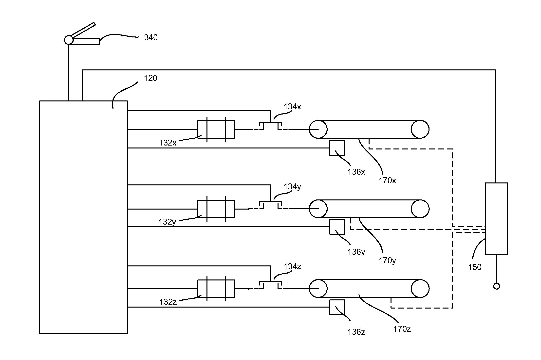
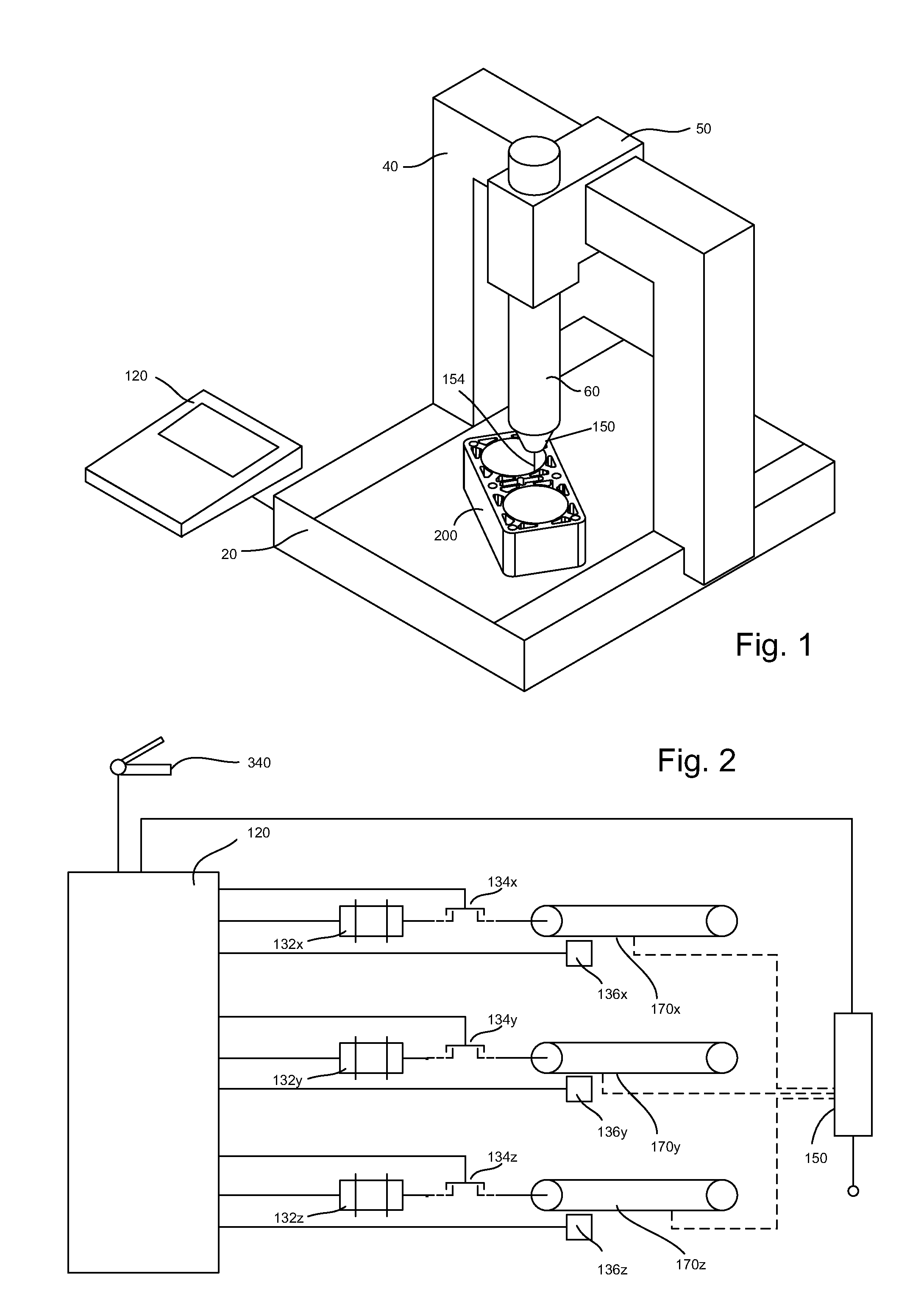
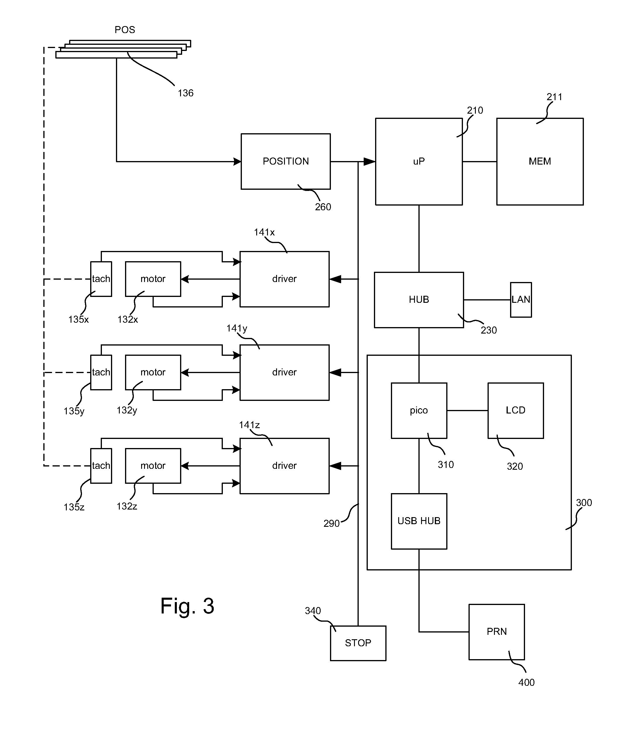
[0016]The following description and figures will refer, for concision's sake to an embodiment of the invention in a Coordinate measuring machine (CMM). It must be understood, however, that the invention is not so limited and is equally applicable to other kind of positioning machines and systems, like for example machine tools or robots, in which a measuring head or tool is connected to a movable controlled platform. Likewise, the following description relates to a machine and the relative motion controller with three linear axes and degrees of freedom, but this is not a limitation of the invention, the latter including positioning system with an arbitrary number of axes, linear or rotational.

[0017]FIG. 1 represents a coordinate measuring machine of a conventional type, with a travelling bridge. A part to be measured is positioned on the table 20. The bridge 40 travels relative to the table 20 along a horizontal axis Y and the carriage 50 can slide on the cross slide of the bridge a...


PUM


Abstract

Coordinate positioning machine or coordinate measuring machine (CMM), with a microprocessor control unit arranged to drive individual axis driver and a proxy module allowing the connection of external devices on a TCP / IP interface. The external devices are used for User interaction, by means of an http server embedded in the microprocessor control unit, or for advanced tasks including tuning and calibration of the dynamic parameters.

Description

REFERENCE DATA[0001]The present application claims priority from European Patent Application EP11168477.5 filed on Jun. 1, 2011, the contents whereof are hereby incorporated by reference.TECHNICAL FIELD[0002]The present invention concerns an automated coordinate measuring machine (CMM) or a computer numerical control (CNC) machine equipped with a measuring probe and, in particular, a motorized coordinate measuring machine provided with a specialized measurement controller and affording greater flexibility in the management, programming and adaptation of the axes movements to take into account changes in the measuring system and of the probe.STATE OF THE ART[0003]It is well known how to use coordinate measuring machines (also called CMM) provided with mobile axes and with an orientable head at the end of which a probe makes it possible to measure the coordinates of the surface of a machined part or of any object, and to extract therefrom information from the measurement of the points...

Claims


Application Information

Patent Timeline
Patent Type & Authority Patents(United States)
IPC IPC(8): G01B5/008
CPCG01B21/047G05B19/00G01B5/008G01B5/012H04L67/025G05B19/402G05B19/414
Inventor JORDIL, PASCALVULLIOUD, BENJAMIN
Owner TESA SE
Why Eureka
Try Eureka