
Plug valve and stem sealing assembly

a technology of stem sealing and plug valve, which is applied in the direction of valve housing, valve operating means/release devices, functional valve types, etc., can solve the problems of loosing the bonnet, fluid leaking from the valve, increasing maintenance time and costly process downtime, etc., to reduce maintenance needs, prevent leakage, and improve the reliability of the valve seal

Active Publication Date: 2014-04-22
AEGIS FLOW TECH L L C
View PDF18 Cites 4 Cited by
  • Summary
  • Abstract
  • Description
  • Claims
  • Application Information

AI Technical Summary

Benefits of technology

[0015]An object of this invention is to provide an improved and more robust plug valve and stem sealing assembly capable of preventing leakage under demanding environmental and operating conditions. Another object of this invention is to provide plug valve and stem sealing assembly that improves the reliability of the valve seal. Still a further object of this invention is to provide a plug valve and stem sealing assembly that reduces maintenance needs. Additional objects and advantages of this invention shall become apparent in the ensuing descriptions of the invention.
[0016]Accordingly, an improved and more robust plug valve and stem sealing assembly capable of preventing leakage under demanding environmental and operating conditions while also improving the reliability of the valve seal. The valve includes a body, a flow-element, a bonnet and a dynamic self-adjusting stem sealing assembly. The body has a first port and a second port with a passage configured to flow a media extending between said first port and said second port. The flow-element is positioned between the first and second port and has a stem configured to actuate the flow-element between a closed position and an open position. The bonnet may be secured to the valve body and configured to secure the flow-element and stem sealing assembly in position. The self-adjusting stem sealing assembly is positioned adjacent to the stem and is configured to prevent media leakage from the valve.

Problems solved by technology

However, over time a valve stem / plug may be frequently moved between the open position and closed position, which may expose the bonnet to rotational stress thereby loosening the bonnet.
This can cause the fluid to leak from the valve, which is very undesirable because it can undermine the ability of the valve to control and isolate flow, which can lead to increased maintenance time and costly process downtime.
Moreover, in recent years, environmental regulations have placed a greater emphasis on reducing leaks and other fugitive emissions from valves in industrial settings by imposing fines and other penalties on facilities that exceed allowable levels making any fluid leakage undesirable.
Although this system can prevent leakage around the plug valve, it also presents problems of its own.
In particular, as a result of exposure to demanding environmental and operating conditions, the integrity of the seal can become reduced over time and make the seals prone to leakage.
For example, valves may be exposed to wide and rapid temperature changes, i.e. thermal cycling, causing its seals to contract and expand rapidly, which may degrade the seal over time and impact the reliability of the valve.
In addition, the reliability of a valve seal may be impacted by vibrations and rotational forces.
For example, during operations, a stem seal is often exposed to rotational forces as a valve is moved between its open and closed position, which can degrade the integrity of the seal.
Additionally, valves are often exposed to high pressure operating conditions and pressure drops, which cause vibrations that may degrade the seal,
Once the seal begins to degrade, fluid often begins to leak from the inside to the outside of the valve.
The valve must typically be removed from service for repair in order to prevent further leakage, which leads to costly process downtime and maintenance.
However, this option requires intervention from operations personnel.
Moreover, the additional force required to tighten the bonnet bolts can damage the valve, its components and significantly increase the valve operating torque.

Method used


Image

  • Plug valve and stem sealing assembly
  • Plug valve and stem sealing assembly
  • Plug valve and stem sealing assembly

Examples


Embodiment Construction

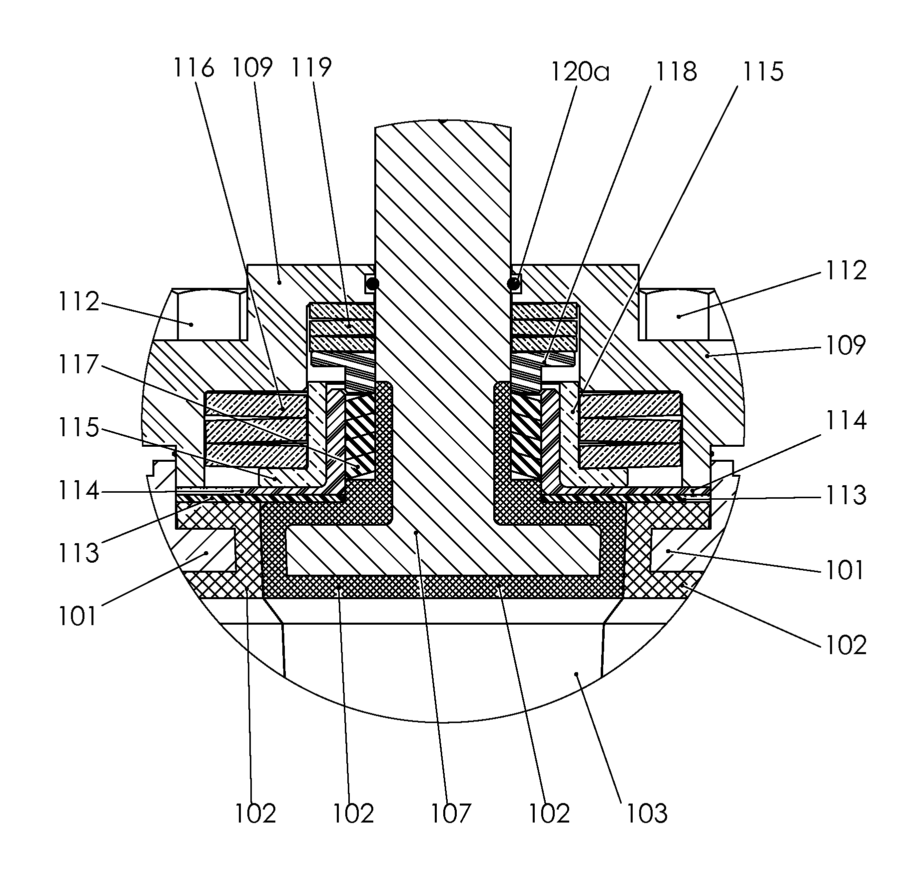
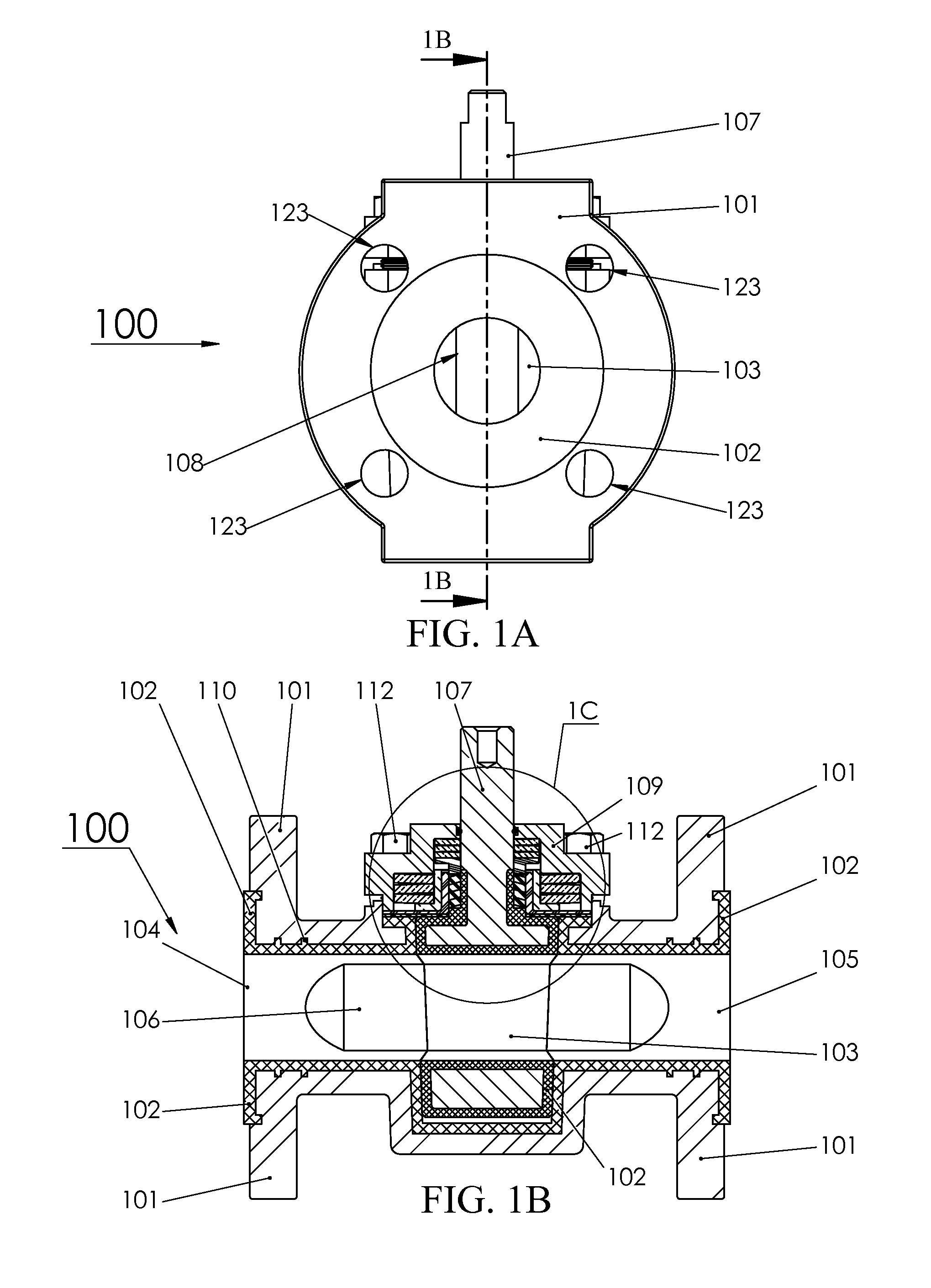
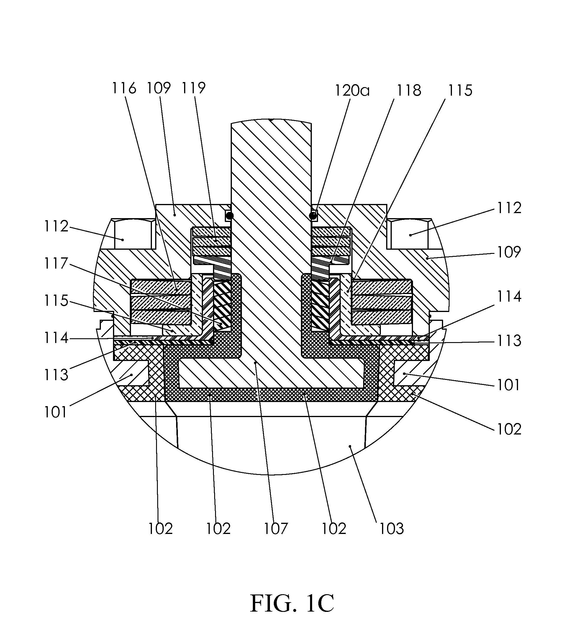
[0028]The claimed subject matter is now described with reference to the drawings, wherein like reference numerals are used to refer to like elements throughout. An embodiment of a valve in accordance with this invention is shown generally in FIGS. 1A-1D at 100.

[0029]With reference initially to FIGS. 1A-1D, the valve (100) comprises a body (101), a flow-element (103) and a stem sealing assembly. The body (101) has a first port (104) and a second port (105) with a passage (106) configured to flow a media (e.g. liquid, gas, vapor, slurry, and so forth) extending between the first port (104) and the second port (105). The body (101) may be single body, three piece body, split body, top entry, or welded. The body (101) may also include a fastening connection (123), such as a flanged bolted connection or threaded connection, at its ends to secure the valve (100) to piping or other equipment. As one of ordinary skill in the art appreciates, the body (101) material may be selected based on ...


PUM


Abstract

A plug valve and stem sealing assembly capable of preventing leakage under demanding environmental and operating conditions while also improving the reliability of the valve seal. The valve includes a body, a flow-element, a bonnet and a self-adjusting stem sealing assembly. The body has a first port and a second port with a passage configured to flow a media extending between the first port and the second port. The flow-element is positioned between the first and second port and has a stem configured to actuate the flow-element between a closed position and an open position. The bonnet may be secured to the valve body and configured to secure the flow-element and stem sealing assembly in position. The self-adjusting stem sealing assembly is positioned adjacent to the stem and is configured to prevent media leakage from the valve.

Description

CROSS-REFERENCE TO RELATED APPLICATION[0001]Not Applicable.STATEMENT REGARDING FEDERALLY SPONSORED RESEARCH OR DEVELOPMENT[0002]Not applicable.THE NAMES OF THE PARTIES TO A JOINT RESEARCH AGREEMENT[0003]Not applicable.INCORPORATION-BY-REFERENCE OF MATERIAL SUBMITTED ON A COMPACT DISC[0004]Not applicable.BACKGROUND OF THE INVENTION[0005]1. Field of the Invention[0006]The present disclosure relates to devices, for regulating flow of a fluid through a passage, either by closing the passage or restricting it by a definite predetermined motion of the flow-element, and more particularly to a plug valve wherein the valve stem and / or actuator is associated with means to pack or seal it to prevent leakage of fluid between the inside and outside of the valve body.[0007]2. Description of Related Art[0008]Plug valves are mechanical devices that are frequently utilized to regulate the flow of fluids such as liquids, gases and slurries over a wide range of temperatures and pressures. These valves...

Claims


Application Information

Patent Timeline
Patent Type & Authority Patents(United States)
IPC IPC(8): F16K41/04
CPCF16K27/00F16K5/0285F16K41/026F16K5/0485F16J15/18F16K17/0493
Inventor CROCHET, SR., KEVIN W.EGER, NORMANROVIRA, III, SIDENY A.
Owner AEGIS FLOW TECH L L C
Learn More