Flow diverting devices

a technology of flow diverting device and thrombosis, which is applied in the direction of prosthesis, ornamental textile articles, catheters, etc., can solve the problems of partially or fully blocked or blocked vessels or other tissues in the body, and achieve the effect of effective and efficient capture of thrombosis

Active Publication Date: 2014-05-06
INSERA THERAPEUTICS
View PDF300 Cites 128 Cited by
  • Summary
  • Abstract
  • Description
  • Claims
  • Application Information

AI Technical Summary

Benefits of technology

[0007]Certain embodiments described herein disclose devices and methods for removing a thrombus or thrombi. These thrombi include, but are not limited to, blood clots (e.g., attached to the blood vessel) and emboli (e.g., floating blood clots), as well as other debris. Several embodiments provide devices comprising multiple bulbs. Vessels or other tissues in the body can become partially or fully clogged or blocked by a thrombus or thrombi. Although some clot retrievers or thrombectomy devices that employ a laser cut hypotube on a distal end of a wire are commercially available, some embodiments disclosed herein do not use laser cut struts and are gentle on the vessel wall, while effectively and efficiently capturing a thrombus in any location in the body. Some devices can be torsional rasped (e.g., wrung or twisted) to help capture thrombi. Certain embodiments described herein disclose devices and methods for treating aneurysms, vascular malformations, fistulas, and the like.

Problems solved by technology

Vessels or other tissues in the body can become partially or fully clogged or blocked by a thrombus or thrombi.
Although some clot retrievers or thrombectomy devices that employ a laser cut hypotube on a distal end of a wire are commercially available, some embodiments disclosed herein do not use laser cut struts and are gentle on the vessel wall, while effectively and efficiently capturing a thrombus in any location in the body.

Method used


Image

  • Flow diverting devices
  • Flow diverting devices
  • Flow diverting devices

Examples


Embodiment Construction

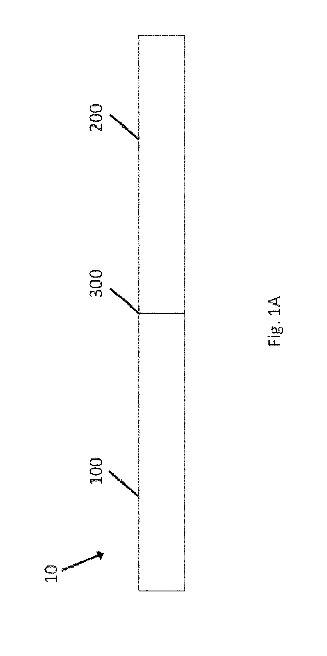
[0343]FIG. 1A is a schematic side elevational view of an example embodiment of a vascular treatment device 10. The device 10 includes a distal portion 100, a proximal portion 200, and a joint 300 coupling the distal portion 100 to the proximal portion 200. In the device 10, the joint 300 couples a proximal segment of the distal portion 100 to a distal segment of the proximal portion 200.

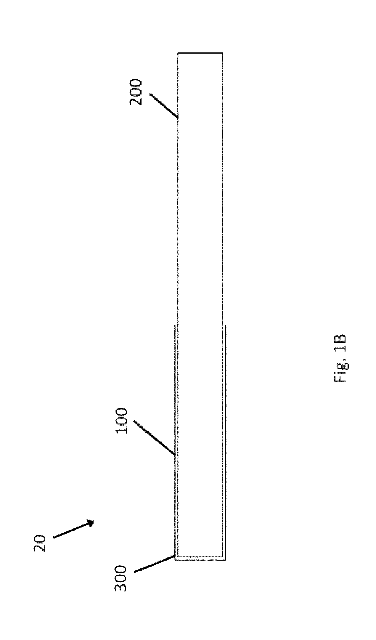
[0344]FIG. 1B is a schematic side elevational view of another example embodiment of a vascular treatment device 20. The device 20 includes a distal portion 100, a proximal portion 200, and a joint 300 coupling the distal portion 100 to the proximal portion 200. In the device 20, the joint 300 couples a distal segment of the distal portion 100 to a distal segment of the proximal portion 200. The proximal portion 200 extends through the distal portion 100.

[0345]FIG. 1C is a schematic side elevational view of yet another example embodiment of a vascular treatment device 30. The device 30 includes a dist...


PUM

PropertyMeasurementUnit
diameteraaaaaaaaaa
diameteraaaaaaaaaa
diameteraaaaaaaaaa

Abstract

Vascular treatment and methods include a plurality of self-expanding bulbs and a hypotube including interspersed patterns of longitudinally spaced rows of kerfs. Joints between woven structures and hypotubes include solder. Woven structures include patterns of radiopaque filaments measureable under x-ray. Structures are heat treated to include at least shapes at different temperatures. A catheter includes a hypotube including interspersed patterns of longitudinally spaced rows of kerfs. Heat treating systems include a detachable flange. Laser cutting systems include a fluid flow system.

Description

INCORPORATION BY REFERENCE TO ANY PRIORITY APPLICATIONS[0001]The present application is a continuation of U.S. patent application Ser. No. 13 / 953,540, filed on Jul. 29, 2013.[0002]Any and all applications for which a foreign or domestic priority claim is identified in the Application Data Sheet as filed with the present application, as well as U.S. patent application Ser. No. 13 / 952,982, filed on Jul. 29, 2013, and U.S. Provisional Patent App. No. 61 / 798,540, filed on Mar. 15, 2013, are hereby incorporated by reference under 37 C.F.R. §1.57.BACKGROUND[0003]1. Field[0004]The present disclosure generally relates to devices, systems, methods for making, and methods for use in vascular procedures such as thrombectomy and / or flow diversion. Several embodiments relate to thrombectomy systems and methods for providing approaches for the treatment of stroke, peripheral vascular disease, coronary artery disease, saphenous vein graft disease, clogged hemodialysis grafts, cerebral venous sinus...

Claims


Application Information

Patent Timeline
Patent Type & Authority Patents(United States)
IPC IPC(8): A61M29/00
CPCA61F2/01A61B19/54B23K26/20A61M2210/12A61B17/221A61F2002/011A61M2207/10B23K26/083A61F2002/018B23K26/1417B23K26/14A61B2017/22034A61M29/00A61B2017/22001D04C1/12A61B2017/22002B23K26/38A61B17/22A61B2017/00778B23K26/1405A61F2/013D04C1/06A61M25/10A61B17/22032A61M1/0031A61M2202/06A61B17/22031B26F3/004A61B17/3207Y10T29/49995A61M2025/0042A61M25/0023A61B2017/22035Y10T82/2521A61M1/008A61B17/32056Y10T156/10Y10T137/85954A61B2017/22067Y10T137/8376Y10T29/49913B23K26/142B23K26/146D04C3/48D10B2509/06A61B17/12109A61B17/12113A61B17/12122A61B17/12172A61B2017/00575A61B2017/00592A61B2017/00606A61B2017/00641A61B90/39A61B2090/3966A61B2017/00526A61F2/011A61M1/74A61M1/84D10B2403/0333B23K26/1435
Inventor JANARDHAN, VALLABHJANARDHAN, VIKRAM
Owner INSERA THERAPEUTICS
Why Eureka
Try Eureka