
Motor drive device, and compressor and refrigerator using same

a technology of motor drive and compressor, which is applied in the direction of electronic commutators, dynamo-electric converter control, domestic cooling devices, etc., can solve the problems of increasing or decreasing the pulsation of a weakening the magnetic flux, and increasing or decreasing the current of the motor, so as to suppress an unstable state, extend the drive range, and high reliability

Inactive Publication Date: 2014-05-06
PANASONIC CORP
View PDF20 Cites 12 Cited by
  • Summary
  • Abstract
  • Description
  • Claims
  • Application Information

AI Technical Summary

Benefits of technology

The present invention provides a drive device for a brushless DC motor that improves stability under high-speed and high-load conditions. The device uses a phase correction unit to maintain the relationship between the motor current and voltage phases, ensuring smooth motor rotation regardless of the load. This results in a more reliable drive under high-speed and high-load conditions, extending the motor's range of operation and minimizing external factors that cause instability. Overall, the device provides a high-reliability solution for driving brushless DC motors.

Problems solved by technology

However, when the load is a predetermined level or more, the rotor is delayed with respect to the commutation, resulting in a magnetic flux weakening state.
That is to say, with reference to the position of the rotor, the phase of the applied voltage and the phase of the current become leading phases with respect to the phase of the induced voltage, resulting in a magnetic flux weakening state.
That is to say, due to the change in the speed of the rotor, the phase of the induced voltage is unstable, and therefore the phase relation between the phase of the applied voltage and the phase of the current may be changed.
Furthermore, there may be increase or decrease in the pulsation of a current of the motor by cyclic acceleration and deceleration, a stop of protection of over-current caused by the occurrence of the current pulsation, and finally, possibility of the out-of-synchronism of the brushless DC motor.
This means that the drive of the brushless DC motor under high-speed and high-load conditions is limited.
In other words, there has been a problem that a drive range cannot be extended (that is, a drive range is narrow).

Method used


Image

  • Motor drive device, and compressor and refrigerator using same
  • Motor drive device, and compressor and refrigerator using same
  • Motor drive device, and compressor and refrigerator using same

Examples


first exemplary embodiment

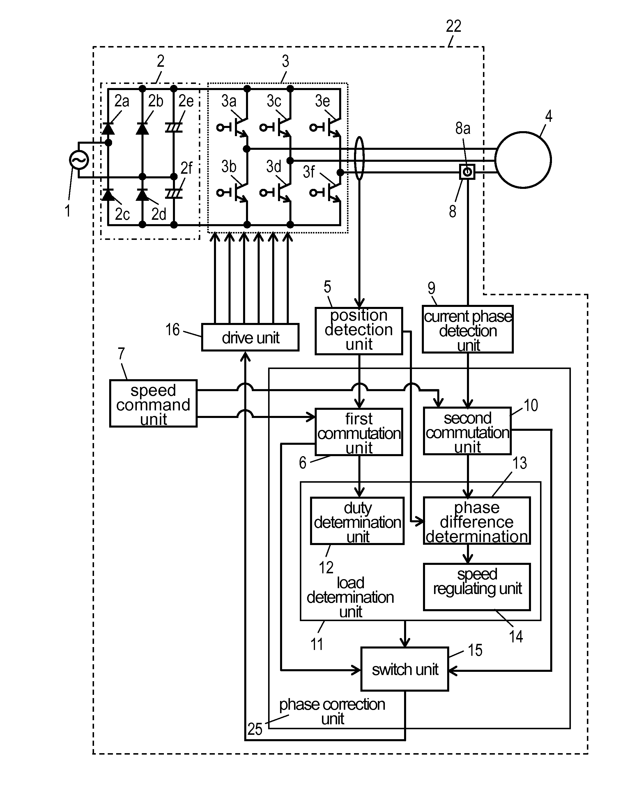
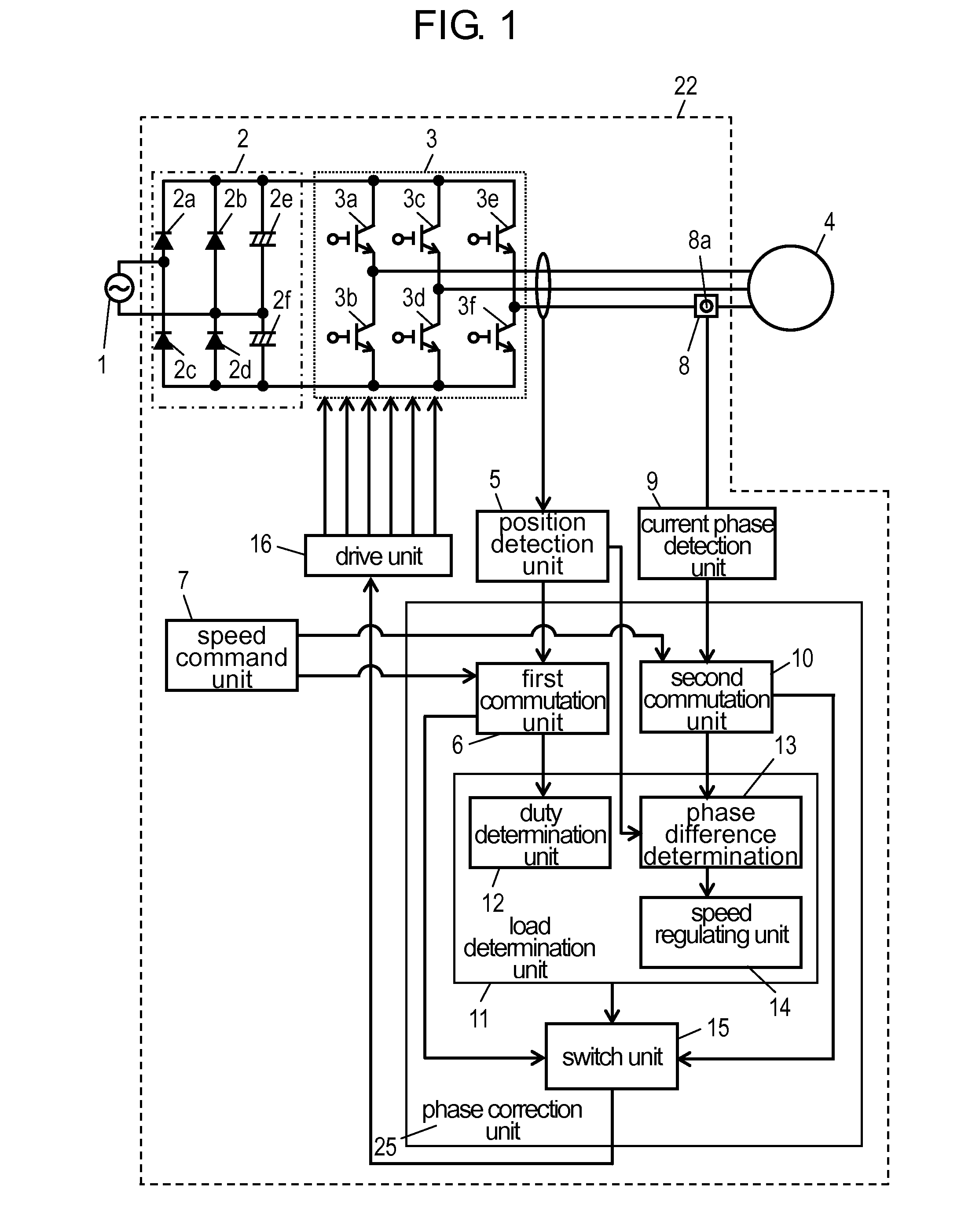
[0029]FIG. 1 is a block diagram showing a motor drive device in accordance with a first exemplary embodiment of the present invention. In FIG. 1, power supply 1 is a general commercial power supply. In Japan, it is a 50 Hz or 60 Hz AC power supply having an effective value of 100 V. Motor drive device 22 is connected to power supply 1 and drives brushless DC motor 4. Hereinafter, motor drive device 22 is described.

[0030]Rectifying and smoothing circuit 2 receives an input from power supply 1 and rectifies and smoothes AC electric power to DC electric power. Rectifying and smoothing circuit 2 includes four bridge-connected rectifier diodes 2a to 2d, and smoothing capacitors 2e and 2f. Inverter 3 includes six switching elements 3a to 3f which are coupled via a three-phase full bridge. Inverter 3 converts DC electric power from rectifying and smoothing circuit 2 into AC electric power, and supplies AC electric power of any voltage and frequency to brushless DC motor 4. Brushless DC mot...

second exemplary embodiment

[0042]A motor drive device in accordance with a second exemplary embodiment of the present invention is described with reference to, for example, FIG. 1. Note here that the same components as those described in the first exemplary embodiment are described with the same reference numerals given.

[0043]In FIG. 1, power supply 1, rectifying and smoothing circuit 2, inverter 3, and brushless DC motor 4 are the same components as those in the first exemplary embodiment. Position detection unit 5 detects a relative position of a rotor of brushless DC motor 4. As a method for detecting the relative position of the rotor of brushless DC motor 4, any methods can be employed. Examples of the method for detecting a zero-crossing point of an induced voltage generated by rotation of brushless DC motor 4 include a well-known method of comparing the size of a voltage of an output terminal of inverter 3 and ½ of a DC voltage of inverter 3 with each other and detecting timing at which the size relati...

third exemplary embodiment

[0083]FIG. 9 is a block diagram showing a refrigerator using a motor drive device in accordance with a third exemplary embodiment of the present invention. In FIG. 9, the same components as those in FIG. 1 are described by using the same reference numerals.

[0084]Brushless DC motor 4 is connected to compression element 24 to form compressor 17. In this exemplary embodiment, compressor 17 is used in a refrigeration cycle. In other words, a high-temperature and high-pressure refrigerant discharged from compressor 17 is transmitted to condensation device 18, and it is liquefied, made to be low pressure in capillary tube 19, evaporated in evaporator 20, and returned to compressor 17 again. Furthermore, in this exemplary embodiment, the refrigeration cycle using motor drive device 22 is used for refrigerator 21, and evaporator 20 cools inside 23 of refrigerator 21.

[0085]In this way, in this exemplary embodiment, brushless DC motor 4 drives compression element 24 of compressor 17 of the re...


PUM


Abstract

Phase correction unit (25) for outputting a commutation signal for switching a winding that allows a current to flow to brushless DC motor (4) and drive unit (16) for outputting a drive signal indicating supplying timing of electric power supplied to brushless DC motor (4) by inverter (3) based on the commutation signal output from phase correction unit (25) are provided so as to maintain a predetermined relation between a phase of a current flowing to a predetermined winding of brushless DC motor (4) and a phase of a voltage. Since brushless DC motor (4) is driven by a signal for holding the predetermined relation between the phase of the current and the phase of the voltage, the stability of drive under high-speed and high-load conditions is enhanced and a drive range is extended.

Description

TECHNICAL FIELD[0001]The present invention relates to a motor drive device for driving a brushless direct current (DC) motor, as well as a compressor and a refrigerator using the same.BACKGROUND ART[0002]A conventional motor drive device carries out control by switching between drive under low-load conditions and drive under high-load conditions in order to extend a drive range of a brushless DC motor. That is to say, in low-load conditions, the conventional motor drive device carries out speed control based on a rotation position of the brushless DC motor by pulse width modulation (PWM) feedback control. Furthermore, a conventional motor drive device disclosed in Patent Literature 1 carries out synchronous drive that switches a phase to be energized of the brushless DC motor in a constant cycle in high-load conditions. FIG. 10 is a block diagram showing the conventional motor drive device described in Patent Literature 1.[0003]In FIG. 10, power supply 101 is a general commercial po...

Claims


Application Information

Patent Timeline
Patent Type & Authority Patents(United States)
IPC IPC(8): H02P6/00H02P6/18F04B49/06F25D11/00H02P6/06H02P6/08H02P6/17H02P6/182
CPCH02P6/142H02P6/181H02P6/18H02P2201/03H02P27/06H02P2205/01H02P23/0027H02P23/009H02P6/15
Inventor TANAKA, HIDEHISATAKEOKA, YOSHINORI
Owner PANASONIC CORP
Learn More