Storage box

a storage box and box body technology, applied in the field of storage boxes, can solve the problems of large accumulation of files and papers, affecting the stacking effect, and the bottom of the box to fail and open when loaded,

Active Publication Date: 2014-05-13
BRIAN TIMOTHY BOLAND +1
View PDF37 Cites 12 Cited by
  • Summary
  • Abstract
  • Description
  • Claims
  • Application Information

AI Technical Summary

Benefits of technology

[0027]Preferably said supporting edge is provided with a length of channel section adapted to fit over said is supporting edge; said channel section acting to strengthen and protect said supporting edge from damage.
[0061]Preferably opposite walls of the wall structure have articulated at their top edge a secondary panel that may be folded down within the box; said secondary panels have toward their midsection a transverse crease such that the lower portion of the fold may be folded back up upon the upper portion so that the edge of the secondary panel terminates at little short of the top edge of the wall and are so positioned to form two support walls for the placement of the notched ends of hanging files; the side edges of the support walls have a short tab that engage reciprocal slots in fold down flaps of adjacent side panels to retain the walls in location; the upper edges of the wall are fitted with channel section lengths to give additional beam strength and to protect the edge from damage by the notched ends of the hanging files.
[0062]Preferably said receptacle having a lid with a downward facing channel section at it's underside periphery such that the channel section releasably engages over the upper edges of the wall structure thereby to enhance structural integrity of said receptacle to increase the load bearing capacity of the walls when receptacles are stacked vertically and maintain walls substantially planar.

Problems solved by technology

It is also a requirement in many jurisdictions that matters relating to a company's transactions be retained for a number of years, causing a large accumulation of files and papers, which must then be retrievably archived.
A disadvantage of these types of storage boxes, is that their bottoms tend to fail and open when loaded.
Also they do not stack well because they do not positively locate one on top of the other, and lack structural integrity to properly support the weight of superior boxes in a stack.
Additionally, any dampness on the floor of the storage area may result in damage to the contents and softening of the lower portion of the side walls of the bottom box leading to possible failure of the walls and collapse of the stack.
However, such structural remedies are a poor use of a natural resource [wood fibre] and significantly increase the cost to the consumer for little net product improvement.

Method used


Image

  • Storage box
  • Storage box
  • Storage box

Examples


first preferred embodiment

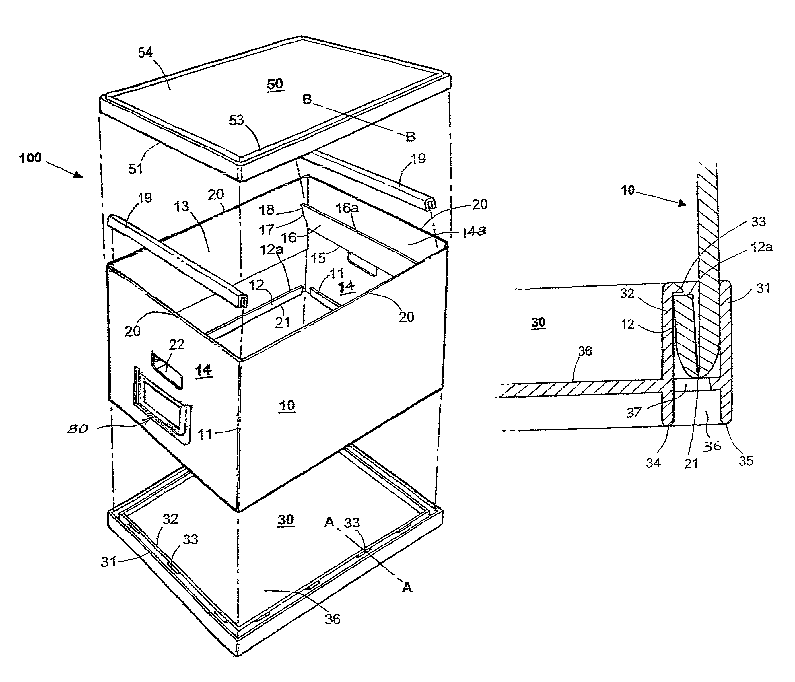
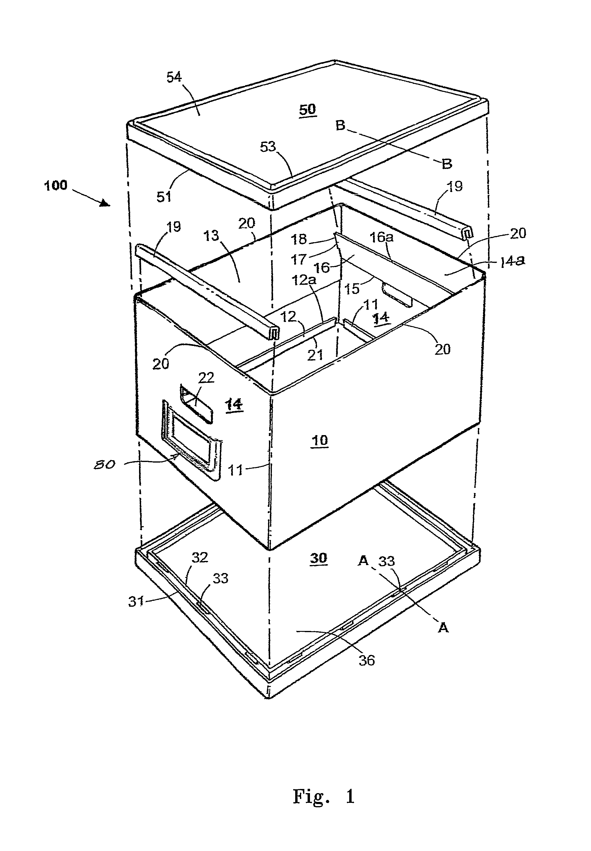
[0084]FIGS. 1,2,4,5,6,7 and 8 show a first embodiment of a storage box 100 according to the present invention, which includes a substantially rigid wrapper 10 forming four articulated side wall panels. As shown in FIG. 6, the side wall panels are pre-cut as a single die-cut piece of fibreboard or other suitable material, provided with preformed folds 11, 15, 20 and 21. An end tab 23 allows the wrapper 10 to be joined at the outer ends, for example by self adhesive strips to form the rectangular box-like form shown in FIG. 1. The joining of the outer ends of the wrapper may be left to a user when the box is erected for use, or may be joined at the manufacturing stage.

[0085]With reference to FIGS. 1 and 6, the upper edges 20 of the side wall panels of wrapper 10, are provided with extension portions to give a double thickness of material to the upper parts of the side wall panels when folded about fold lines at edges 20. The lower edges 21 of the side wall panels are likewise, in this...

second preferred embodiment

[0097]In a second fore of the invention shown in FIGS. 7 and 8, the wrapper 10 has an additional fold line 24 down the centre of the two opposite longer side walls. Folds 24 allow the wrapper 10 to be folded into a shorter pack and nested within the periphery of the inverted lid 50. As can be seen in FIG. 8, inverted lid 50 may in turn be nested within the inverted base 30 to provide a compact flat assembly which may be packaged for example by shrink wrapping for point of sale.

third preferred embodiment

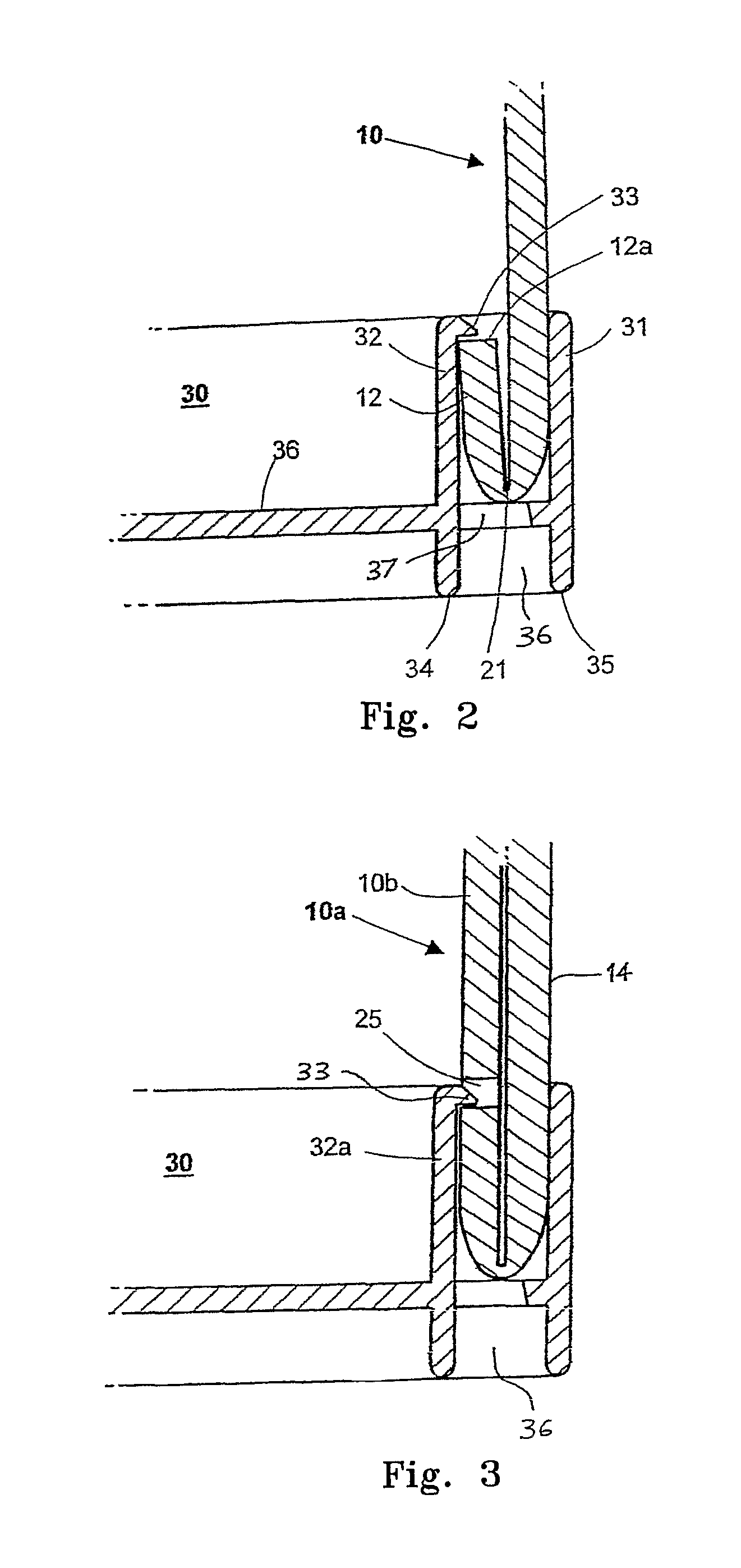
[0098]With reference to FIG. 3, in a further preferred form of the invention, attachment of the wrapper 10 with the plastic base 30 is effected by punched holes 25 provided in extended folded portions 10b engaging with the afore described protrusions 33. Although FIG. 3 shows the punched holes 25 in the upturned portions 10b, holes 25 could alternatively be formed in end wall panel 14, Retaining protrusions 33 would then be located at the inner edges of the outer wall 31 of the base 30.


PUM


Abstract

A stackable and collapsible storage box (100) comprising a foldable wrapper (10) having side wall and end wall panels which are releasably retained within a peripheral channel (30a) on a separate base portion (30). The wall panels have lower extension portions (11, 12) that are folded upwardly to provide a double thickness and these lower extension portions have an upper edge (12a) or apertures (37) that engage with short protrusions (33) formed on an inner wall (32) of the channel to retain the panels. The end wall panels have upper first and second extensions portions (14a, 16) that are respectively folded inwardly and upwardly to provide a support edge (16a) to support hangers for hang files. The support edge can be strengthened with a channel section (19). The box can have a lid (50) has a ridge (53) to compliment channel (36) on the base portion to allow stacking.

Description

RELATED APPLICATIONS[0001]This application is the U.S. National Phase of PCT / AU2005 / 001112 filed Aug. 1, 2005 and claims priority to Australian Provisional Patent Application No. 2004904284 filed Aug. 2, 2004, which are hereby incorporated herein by reference in their entirety.[0002]The Present Invention Relates to Stackable Boxes suitable for use as general storage boxes and / or as archive boxes for documents and hanging files, and which are manufactured in a flat pack form to be easily assembled by the consumer.BACKGROUND[0003]Market Researchers know that the average American consumer currently has some twenty thousand individual possessions in their homes and say that this number is growing yearly. A good percentage of these possessions are not often used and are stored indefinitely.[0004]Companies generally wish to maintain archived copies of past transactions. It is also a requirement in many jurisdictions that matters relating to a company's transactions be retained for a numbe...

Claims


Application Information

Patent Timeline
Patent Type & Authority Patents(United States)
IPC IPC(8): B65D43/08B65D6/28B65D5/36
CPCB42F15/007B65D11/1853B65D15/22B65D15/08
Inventor BOLAND, BRIAN, TIMOTHY
Owner BRIAN TIMOTHY BOLAND
Why Eureka
Try Eureka