Discharge device for vehicle

a technology for discharging devices and vehicles, applied in the direction of electric devices, propulsion by batteries/cells, transportation and packaging, etc., can solve the problems of electricity supply from the electricity source to the electric circuit,

Inactive Publication Date: 2014-05-13
TOYODA GOSEI CO LTD +1
View PDF26 Cites 11 Cited by
  • Summary
  • Abstract
  • Description
  • Claims
  • Application Information

AI Technical Summary

Benefits of technology

[0009]Accordingly, it is an objective of the present invention to provide a discharge device for a vehicle that is reliably activated to discharge capacitors when an abnormality related to a collision of a vehicle is detected.

Problems solved by technology

When an abnormality related to a collision of the vehicle is detected, the electricity supply from the electricity source to the electric circuit is stopped.

Method used


Image

  • Discharge device for vehicle
  • Discharge device for vehicle
  • Discharge device for vehicle

Examples


first embodiment

[0025]A discharge control device for a vehicle according to a first embodiment of the present invention will now be described with reference to FIGS. 1 to 5.

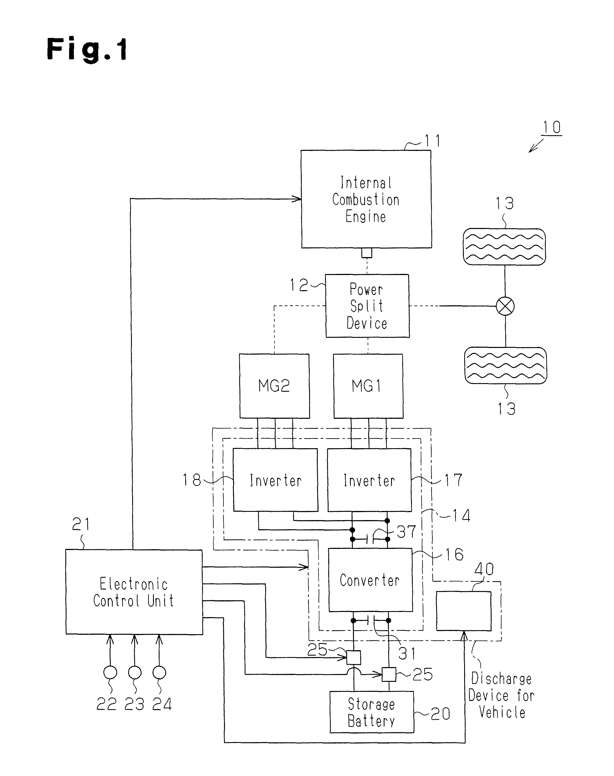
[0026]FIG. 1 schematically shows a hybrid vehicle (hereinafter, simply referred to a vehicle), to which the discharge device for a vehicle according to the present embodiment is applied. As shown in FIG. 1, a vehicle 10 includes, as a power source, an internal combustion engine 11, a first motor-generator MG1, a power split device 12, and a second motor-generator MG2. Three-phase alternating current synchronous motors may be used as the first and second motor-generators MG1, MG2. The power split device 12 includes a planetary gear train and distributes the power generated by the internal combustion engine 11 to the first motor-generator MG1 and drive wheels 13. The second motor-generator MG2 chiefly functions as an electric motor and generates auxiliary power for driving the drive wheels 13 separately from the power of the inter...

second embodiment

[0072]A discharge device for a vehicle according to a second embodiment of the present invention will now be described with reference to FIGS. 6 and 7.

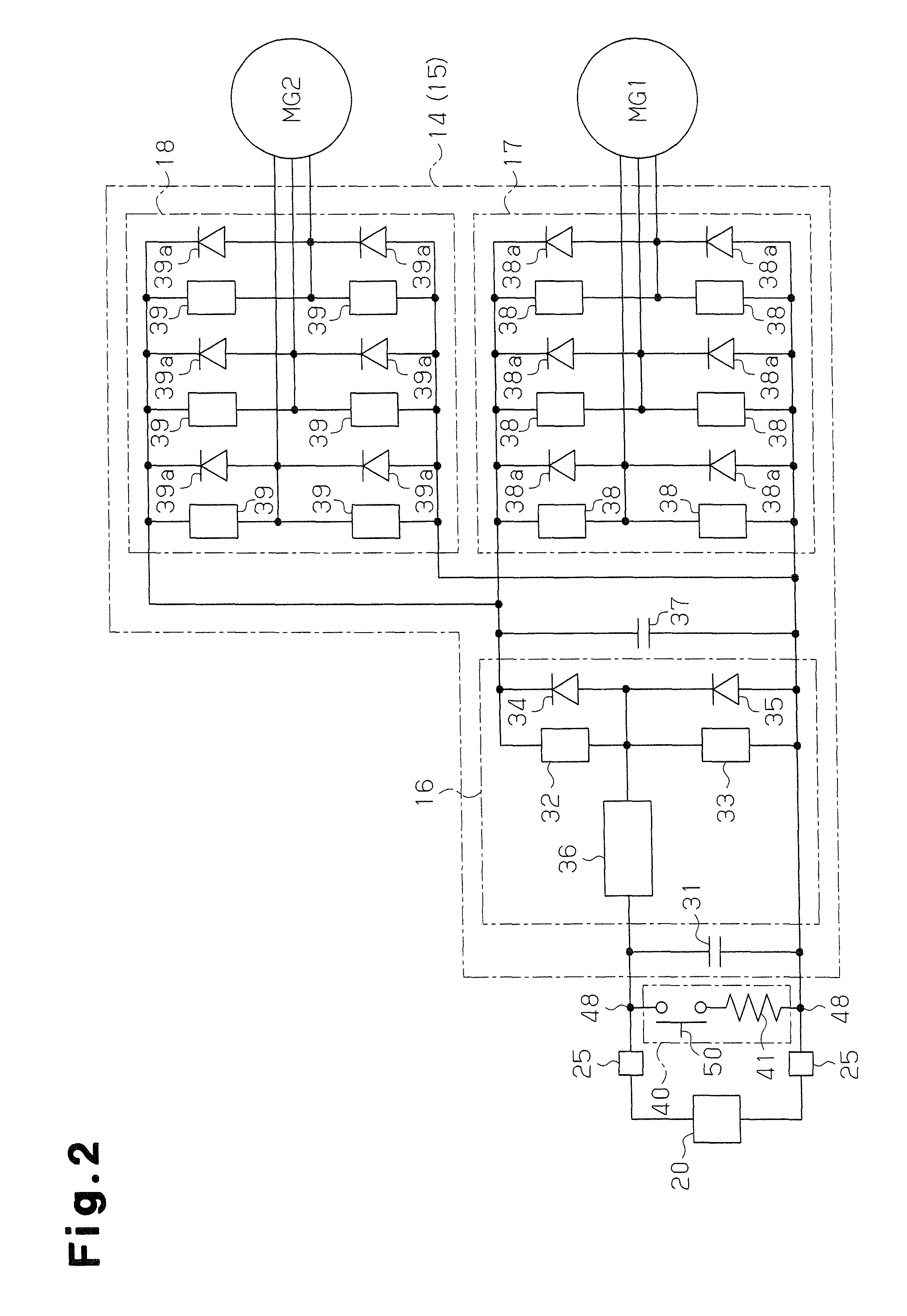
[0073]In the second embodiment, the second capacitor 37 is discharged by the discharge mechanism 40 in addition to stopping of electricity supply from the storage battery 20 to the PCU 14 by activating the breakers 25 when a collision of the vehicle 10 is detected.

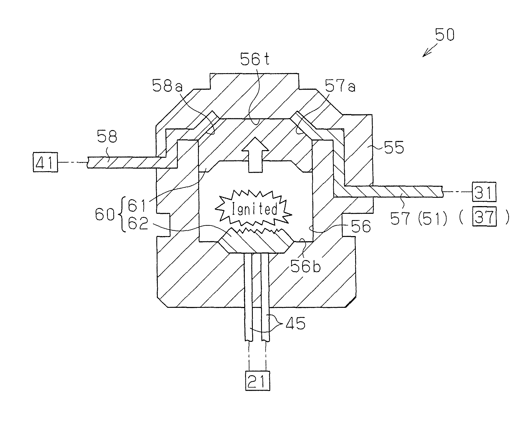
[0074]The discharge mechanism 40 has an elongated discharge mechanism case 42, a switch 50, and a discharging resistor 41. The switch 50 and the discharging resistor 41 are arranged in the discharge mechanism case 42 and connected to each other in series. A first bus bar 51 is connected to the switch 50, and a second bus bar 52 is connected to the discharging resistor 41. A part of the first bus bar 51 and a part of the second bus bar 52 include connecting terminals 51a, 52a, respectively. The terminals 51a, 52a extend through side plates 43 of the discharge mechanism case 4...

third embodiment

[0080]A discharge device for a vehicle according to a third embodiment of the present invention will now be described with reference to FIGS. 8 to 10.

[0081]In the third embodiment, the first capacitor 31 and the second capacitor 37 are discharged by a common discharge mechanism 40 in addition to stopping of electricity supply from the storage battery 20 to the PCU 14 by activating the breakers 25 when a collision of the vehicle 10 is detected.

[0082]As shown in FIG. 8, the discharge mechanism 40 has an elongated discharge mechanism case 42, a switch 50, and a discharging resistor 41. The switch 50 and the discharging resistor 41 are arranged in the discharge mechanism case 42 and connected to each other in series. Two first bus bars 51, 71 are connected to the switch 50, and a second bus bar 52 is connected to the discharging resistor 41. A part of one of the first bus bars 51 and a part of the second bus bar 52 include connecting terminals 51a, 52a, respectively. The terminals 51a, ...


PUM


Abstract

A power control unit (PCU) case accommodates an electric circuit of a PCU, which includes a first capacitor and is operated by electricity supply from a storage battery. In the electric circuit, a first bus bar is connected to a part in the vicinity of the anode of the first capacitor, and a second bus bar is connected to a part in the vicinity of the cathode of the first capacitor. A discharge mechanism is formed by connecting in series a switch activated by an explosive actuator and a discharging resistor. The discharge mechanism is integrally fixed to the PCU case. When a collision of the vehicle is detected, the discharge mechanism short-circuits the first bus bar and the second bus bar with each other through the activation of the switch. Accordingly, the discharge mechanism is connected in parallel with the first capacitor, so that the discharging resistor discharges the first capacitor.

Description

BACKGROUND OF THE INVENTION[0001]The present invention relates to a discharge device employed in a vehicle that includes an electric circuit having capacitors, and forcibly stops electricity supply to the electric circuit when an abnormality related to a collision is detected. More specifically, the present invention relates to a discharge device that forcibly discharges capacitors, in addition to stopping the electricity supply, when an abnormality is detected.[0002]In recent years, vehicles such as hybrid vehicles, electric vehicles, and fuel cell vehicles have been equipped with in addition to motors and a storage battery, which function as power source, an electric circuit for driving the motors with electricity from the storage battery. The electric circuit includes a converter and inverters. The converter raises the voltage of the electricity supplied from the storage battery, and outputs the electricity to the inverter. The inverters convert the received direct-current electr...

Claims


Application Information

Patent Timeline
Patent Type & Authority Patents(United States)
IPC IPC(8): B60L1/00
CPCB60L2270/20B60L3/04Y02T10/6217Y02T10/7225B60L11/14B60L2210/40B60L11/123B60L2220/14Y02T10/7022Y02T10/7241B60L3/0069Y02T10/7077B60L3/0007Y02T10/7005B60L2210/14B60L50/16B60L50/61Y02T10/62Y02T10/70Y02T10/7072Y02T10/72
Inventor FUKUYAMA, TAKAKISUZUKI, SHIGEYUKIKITANO, EIJI
Owner TOYODA GOSEI CO LTD
Why Eureka
Try Eureka